


Mold-Filling Ability of Aluminum Alloy Melt during the Two-Step Foaming Process
[H. Wang1 , Y.M. Zhang2 , B.C. Zhou1 , D.H. Yang3 , Y. Wu1, *  , X.J. Liu
1 , Z.P. Lu1, * ]
, X.J. Liu]
|
|


For the two-step foaming method, one of the most cost-effective ways to fabricate three-dimensional shaped aluminum alloy foams with dense outer surface skin, it is crucial to describe and predict the mold-filling behavior of the shaped aluminum alloy foams with a favorable pore-distribution accurately. In this paper, a mold-filling model for semi-solid aluminum alloy foams was initially established and subsequently employed to predict the filling height, which represents the mold-filling ability of semi-solid aluminum alloy foams in a specially designed tube-like mold. Our results indicate that the proposed model can be applied to characterize the mold-filling property of aluminum alloy melts in a quantitative manner. Theoretically, our findings actually provide a guideline for mass-production of the shaped aluminum alloy foams by using the two-step foaming process.
Metal foam constitutes a new category of attractive materials, which exhibits a unique combination of physical, mechanical, thermal, acoustic and electro-magnetic properties[1, 2, 3, 4]. Particularly, structural shaped aluminum alloy foams (SAAFs) used as the ultra light load-bearing units with complex geometric outlines, i.e., a component integrated dense outer skins with aluminum alloy foams inside, normally shows a relative low density, high stiffness, good energy absorption and electro-magnetic shielding. Such sandwiched light-weight materials have drawn extensive attention in automobile, shipment, construction and aerospace industries from the viewpoint of environmental and energy preservation[5, 6, 7, 8, 9].
Up to date, several approaches have been proposed to fabricate the SAAFs, including powder compact foaming method[10], pre-straining method[11], high pressure casting[12], metallurgical bonding method[13], GASAR method[14], and so on. However, many experimental results have shown that it is difficult to manufacture the SAAFs with a high porosity (> 80%) and uniform pore-structure by the aforementioned methods due to their complicated processes and shortage of mold filling ability. Recently, a special method, namely the two-step foaming (TSF) method[15, 16], was developed. Specifically, a semi-foamed aluminum alloy with a low porosity as a precursor containing undecomposed TiH2 was first prepared by ALPORAS© route[17]. Subsequently, the TiH2-containing alloy foam was placed inside a specially designed mold and reheated up to a certain temperature. During the reheating process, progressive H2 evolution from the partial decomposition of the TiH2 made the precursor foaming again to fill up the mold. Eventually, SAAFs with a homogeneous pore-structure could be obtained after cooling.
Nevertheless, the solid-liquid-gas state of aluminum melt foams affects the heat transfer and solidification process during TSF significantly, which can lead to formation of a large number of gas bubbles inside the melt if the progressive H2 evolution from the partial decomposition is out of control. Some models have been proposed to simulate the foam formation and evolution with modified cellular automata considering with effect factors, such as the foaming time, temperature, atmospheric pressure, gravitational force, viscosity of the melt and surface tension, etc.[18]. However, the present understanding of the influence and the mutual interactions is rather poor and mainly grounded on empirical knowledge. Similarly, this complexity severely limits widespread uses of the TSF method as one of the mass-production routes for manufacturing SAAFs. Therefore, it is critical to describe the mold-filling behavior of the aluminum alloy melt foam with a favorable pore-distribution. In this paper, a mold-filling model for semi-solid aluminum alloy foams was established, in which only driving force and resistance of the melt were considered. We have applied this model to predict the mold-filling ability of a semi-foamed aluminum alloy in a specially designed tube-like mold. Our results indicate that the current model is capable of quantitatively characterizing the mold-filling properties of aluminum alloy melt foams. Finally, a guideline for mass-production of SAAFs by using the TSF method is also proposed.
Commercial aluminum alloy (Ca: 1.40, Ti: 1.50, Cu: 4.55, Mn: 0.35, Zn: 0.20, Zr: 0.20, Al: Bal., and compositions are in weight percentage) was used as the matrix material for preparing the aluminum alloy foam. Among which, Ca and Ti composition from Ca particles (purity > 99.9 wt%, 100 mesh) was selected as the thickening agent and the as-received TiH2 powder (purity > 99.9 wt%) with a size of 300 mesh was chosen as the blowing agent, respectively.
The steel tube-like mold (as shown in Fig. 1(a)) for preparing the shaped-aluminum alloy foam consists of two cylinders with a diameter of 28 and 82 mm, respectively. The cylinders were assembled by bolts. The fabrication process of shaped aluminum alloy foams by the TSF method consists of two steps. First, TiH2 was added in the thickened aluminum alloy melt by vigorous stirring and then the aluminum alloy melt started to foam, which is defined as the first foaming stage. The purpose of this stage is to homogeneously distribute the TiH2 powders in the aluminum alloy melt. After that, the melt foam was water-quenched. Subsequently, the aluminum alloy foam containing residual TiH2 was used as the precursor, and was placed in the steel tube-like mold and heated up to a certain temperature (i.e., 943-1123 K). The gas gradually released from the decomposition of the residual TiH2 powders made the precursor foaming again to fill up the steel mold until the shaped aluminum alloy foam was finally formed.
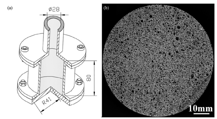 | Fig 1. Mold for the second foaming step (a) and the pore structure of the precursor after the first foaming step (b) |
Specifically, during the first-step foaming process, in order to increase the viscosity of the aluminum alloy melt, 1.5 wt% Ca was added by an impellor with a speed of 450 r/min for 10 min. After the melt thickening, 0.5-1.5wt% TiH2 was added by vigorous stirring with an impellor rotation speed of 1000 r/min for around 30-80 s[19, 20]. Then the melt foams were water-quenched immediately, and the obtained foams were used as the precursors whose porosity, Pr1, was around 51.5% [21]. Fig. 1(b) shows the cross-sectional morphology of the precursor with the porosity 51.7%, which displays a homogeneous fine pore distribution.
During the second foaming stage, the precursors were cut into the size of Φ 82 mm × 80 mm by an electro-discharging machine and completely filled the lower cylinder of the steel mold (as shown in Fig. 1). Subsequently, the loaded mold was preheated to the temperature of 623-853 K for 10-30 min, and then placed into a furnace with the temperature of 943-1123 K avoiding the excessive temperature difference inside of precursors. The precursors were foamed to eventually fill up the upper cylinder of the mold. Finally, the mold was cooled rapidly while the height of the filling stopped increasing and the porosity of the foam, i.e., Pr2, was measured.
Three phases, i.e., solid, liquid and gas, actually coexist in a semi-solid aluminum alloy foam. The model-filling process of aluminum alloy melt foams is a rheological filling process of sticky, plastic non-Newtonian fluid, which is different from either the flow deformation process of Newtonian fluids during liquid forming or the plastic deformation process during solid plastic forming because the mixed slurries are composed of solid particles and gas bubbles suspending in the alloy melt[22]. The nonlinear relationship between an applied shear stress and a shear rate during the ongoing rheological process is characterized by rheological characteristics of pseudo-plastic fluids. This rheological model can be described by Bingham body model as follows[23]:
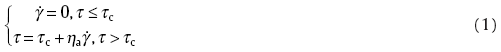
where 


Fig. 2(a) is the schematic illustration of the rheological mold-filling of a semi-solid aluminum alloy foam in a circular tube, where P is the filling pressure. Generally, due to existence of the ST. Venant, a perfectly plastic solid proposed by Saint Venant and pseudo-plastic fluids, the alloy melt does not flow when a shear stress on the tube-wall, which is produced by the filling pressure, is less than a critical shear stress. When the pressure P is equal to the critical shear stress, τ c, the whole alloy filling flow in the circular tube can be regarded as a rigid body because when r < R as shown in Fig. 2(a), and the shear stress of the melt foam, τ , is less than τ c. When the shear stress of the cylindrical surface (where r = r0) produced by pressure is τ c, there exists a flow inside the alloy melt in the range from r0 to R. However, there is no relative movement between each point of the flow in the cylinder from 0 to r0, i.e., every point of the flow is in the sliding of a whole. In other words, the filling speeds at each point of the flow in the cylinder of the circular tube are the same.
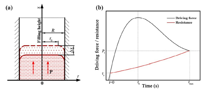 | Fig 2. Illustration of the semi-solid aluminum alloy foam filling process. (a) Sketch of rheological filling of a semi-solid aluminum foam in a round tube, and (b) the relationship between the filling force and the filling time |
The filling driving force (Pd) of the semi-solid aluminum alloy foam is the internal pressure caused by the H2 released from the thermal decomposition of the residual TiH2 in the precursor. In the mold-filling process, the resistance of filling is the sum of the atmospheric pressure (P0), the pressure caused by the gravity of the filling in the upper cylinder tube (Pf) and the additional pressure caused by the curved surface tension (Pt) of the aluminum alloy foam melt.
As shown in Fig. 2(b), in the beginning of the mold-filling process, the filling resistance equals to the critical shear stress τ c because both the filling height and filling time are zero, i.e. x = 0 and t = 0. The filling height, which is applied to characterize the mold-filling ability, increases due to H2 released from the TiH2 decomposition. Accordingly, the filling resistance also rises because of the increase in the Pt and Pf as the filling proceeds. The driving force is determined by the TiH2 decomposition behavior, which increases first and then drops until the equilibrium between the filling force and the resistance is reached, i.e. both the filling driving force and the filling resistance approach to Pl, the pressure of the alloy melt foam at the bottom of the upper cylinder mold when the filling height does not ascend. Consequently, the filling process is finally stopped and the filling height achieves its upper limit.
As mentioned in Section 3.1, the semi-solid aluminum alloy foam is a non-Newtonian fluid with a high apparent viscosity and shear rate during the mold-filling process. The melt foam filling flow can be regarded as a laminar flow. In order to discuss the filling process in the upper cylinder tube, four assumptions are proposed; 1) the filling melt has no radial and tangential velocity components, 2) its radial and axial temperature are uniform, i.e., temperature is a constant in the furnace, 3) the moving velocity of the melt frontier, 
The energy equation in the cylindrical coordinate system and the state equation of a non-Newtonian fluid flowing axially along the x direction in the upper cylinder mold can be expressed by Eqs. (2) and (3), respectively[24]:
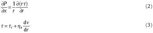
Substituting Eq. (3) into Eq. (2), the expression for flow quantity of the laminar flow, Q, in a cylinder tube is obtained as follows:

where R is the radius of the upper cylinder mold as shown in Fig. 2(a), and Δ P is change of pressure of aluminum alloy melt at the bottom of upper cylinder tube during foaming process.
Since the quantity of the laminar flow can also be expressed as
The expression for the pressure change of the semi-solid aluminum alloy foam in the cylinder tube can be derived from Eqs. (4), (5) and (6):
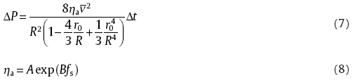
The apparent viscosity is an important indicator to describe the rheological behavior of the semi-solid melt slurry. Hence, in this study, the apparent viscosity, η a, is used to characterize the rheological properties of the semi-solid aluminum alloy melt foam. The previous experiments showed that the apparent viscosity increases by increasing of the fraction of solid particles inside the aluminum alloy melt[25]. Especially, when the solid fraction exceeds a critical value, the apparent viscosity will begin to rise rapidly and consequently, the filling process becomes difficult to be controlled. Generally, the apparent viscosity can be expressed by Eq. (8), where both A and B are coefficients related with material properties, shear rate and shear stress, which can be obtained through linear regression of the η a-fs curve, where fs is the fraction of solid aluminum alloy in the material[25].
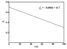
As the filling proceeds, the solid fraction in the semi-solid aluminum alloy foam decreases continuously. The solid fractions at different time period, t, can be measured by the thermal analysis. Then the relationship between the solid fraction fs and the filling time t can be determined by the following relationship (as shown in Fig. 3):

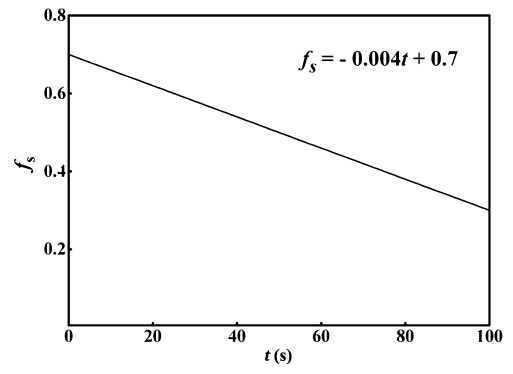 | Fig 3. Relationship between the fractions of solid in the aluminum alloy melt foam and the filling time |
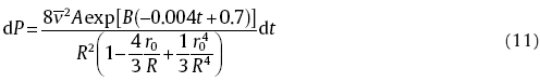
Submitting Eq. (9) to Eq. (8) yields:

Substituting Eq. (10) into Eq. (7), the expression for the filling resistance of the melt along the filling length can be obtained as follows:
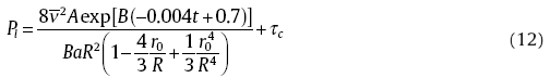
When the filling is completed, the pressure can be obtained after integrating Eq. (11) with the boundary conditions, i.e., t=tmaxt=tmax and P=PlP=Pl, which is shown below:
In the second foaming and filling process, the bubble expansion resistance mainly consists of three parts: 1) static pressure, Ps, gravity of the aluminum alloy foam melt, 2) additional pressure, Pt, caused by surface tension of the melt and 3) atmospheric pressure, P0. When the filling stops, the balance is reached between the filling drive force and resistance of the bubble expansion, i.e.,

where Ps=ρ AlgH, ρ Al is the density of the aluminum alloy matrix and H is the filling height.
At the equilibrium state, the maximum of the filling height, Hmax, which is the mold-filling ability of the semi-solid aluminum alloy foam can be calculated from Eqs. (12) and (13):
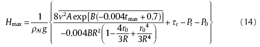
Because r0< R, then 
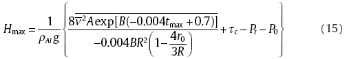
It can be seen from Eq. (15) that the filling height, Hmax is mainly related to the internal pressure, the filling speed, material properties of the mold, the shape and size of the thin circular tube and the critical shear stress of the semi-solid alloy melt at the bottom of the upper tube.
Simulation and validation of our theoretical analysis were carried out, and the constants for theoretical calculations are listed in Table 1 and some parameters such as ρ Al, ν , A and τ c were taken from Ref. [26].
| Table 1 The parameters for theoretical calculations |
With the aforementioned parameters, both of which are constants, the theoretical value of the filling height can be calculated according to Eq. (15). In addition, the aluminum melt precursors added with 0.5-1.5 wt% TiH2 and a similar porosity of 51.5% were used for measuring the actual filling height. Hereby, the porosity content of the alloy foam, Pr, was measured from its mass (M) and volume (V) using the following equation:
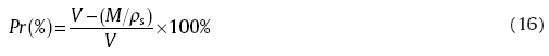
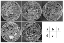
where ρ s is the density of aluminum alloy (2.78 g/cm3). Table 2 lists the filling heights determined both theoretically and experimentally as a function of the TiH2 content and Δ Pr which is the porosity difference between the precursors (Pr1) and the filling (Pr2), along with the difference between the experimental and theoretical values. Fig. 4 shows typical cross-sectional morphology of the resulting samples 1-4, 2-3, 3-3, 4-4 and 5-4 in Table 2. As can be seen, the porosity of all the specimens after the second foaming stage was increased to the range of 70.9% to 91.6%, and there the filling height is strongly dependent on the added TiH2 content.
| Table 2 Comparison between theoretical and experimental values of the filling height of aluminum alloy foams with different TiH2 contents |
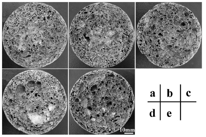 | Fig 4. Typical cross-sectional morphology of the aluminum foams (a) 1-4, (b) 2-3, (c) 3-3, (d) 4-4 and (e) 5-4 shown in Table 1, and the porosity of these specimens is 70.9%, 83.6%, 86.9%, 84.8% and 91.6%, respectively. |
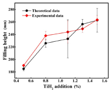
To further demonstrate dependence of the filling height on the TiH2 content, the average filling height as a function of the TiH2 content is plotted in Fig. 5. For a given porosity of the precursor, the filling height increases with the increase of the TiH2 content, which is consistent with the theoretical predication. Moreover, it can be seen that even if the TiH2 content remains unchanged, the porosity after the filling process also slightly changed, which is due to the precursor preparation process. Nevertheless, the difference of the filling height between theoretical and experimental results was marginal, and the maximum deviation is no more than 8.9%, which undoubtedly validates our model and analysis. The observed differences are mainly from the assumptions in which some parameters are simplified. For example, the filling speed is considered to be a constant and the shear stress is assumed to change uniformly along the axis. Moreover, the simplification to obtain Eq. (15) also has an influence on the discrepancy between the experimental heights and theoretical calculations. Furthermore, the differences in temperature fields during the filling of the second foaming process also have some influences on the filling heights.
 | Fig 5. Relationship between the TiH2 content in the aluminum alloy foam and the mold-filling height |
So far, the TSF approach is one of the most economical and efficient methods for preparation of shaped aluminum alloy foam components with dense outer skins. Furthermore, because of the dense skin, the strength of the shaped material is usually higher than that of the one without dense skin. Fig. 6 shows strength comparison between the shaped aluminum alloy foams with and without dense outer skin as a function of porosity. Typical compressive stress-strain curves of the metallic foams with a dense skin are displayed in the inset of Fig. 6. As shown, the fracture strength of both types of samples decreased with the increase of the porosity, but the shaped foams with dense outer skins are always stronger than the sample without a dense skin at any given porosity. Interestingly, the strength of the foams with dense skin decreased more slowly as the porosity is increased; For example, the ratio of the strength values at the low porosity of 70.9% for two kinds of metallic foams is 1.87 (i.e., 36.5 MPa to 19.7 MPa) while, increases to 3.76 at a high porosity of 91.6% (i.e., 12.8 MPa to 3.4 MPa). These results demonstrate that the outer skin plays a critical role in strengthening shaped aluminum alloy foams.
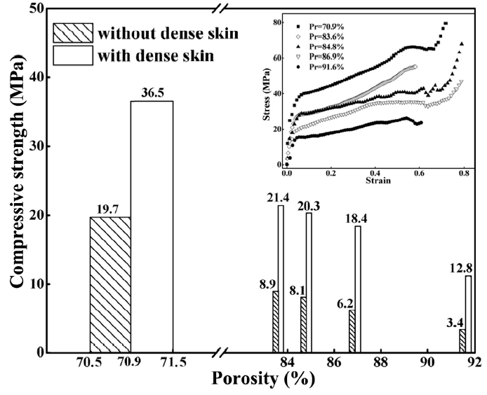 | Fig 6. Strength comparison of the shaped aluminum alloy foams with and without dense outer skins as a function of porosity. Inset is compressive stress-strain curves of typical foams with a dense skin |
Shaped aluminum alloy foams with outer skins were successfully fabricated by the TSF method, and a model was proposed to evaluate their filling ability during the TSF process. Our results showed that the difference between the theoretical calculation and the experiment results is within 8.9%, confirming that our model is capable for predicting the filling height and can be regarded as a guideline to fabricate the SAAFs for mass-production by using the TSF process.
This work is supported by 111 Project (Grant No. B07003), the Program for Changjiang Scholars and Innovative Research Team in University (Grant No. IRT_14R05), the Fundamental Research Funds for the Central Universities (Grant No. FRF-SD-12-004A), the Special Scientific Research Fund for Doctoral Program of the Ministry of Education of the People's Republic of China (Grant No. 20110006110029), Beijing Higher Education Young Elite Teacher Project and the Research Project of the State Key Laboratory for Advanced Metals and Materials, University of Science and Technology Beijing (Grant No.2011-Z13).
| [1] |
|
| [2] |
|
| [3] |
|
| [4] |
|
| [5] |
|
| [6] |
|
| [7] |
|
| [8] |
|
| [9] |
|
| [10] |
|
| [11] |
|
| [12] |
|
| [13] |
|
| [14] |
|
| [15] |
|
| [16] |
|
| [17] |
|
| [18] |
|
| [19] |
|
| [20] |
|
| [21] |
|
| [22] |
|
| [23] |
|
| [24] |
|
| [25] |
|
| [26] |
|