

Formation of TiN Grid on NiTi by Laser Gas Nitriding for Improving Wear Resistance in Hanks' Solution
[C.H. Ng, O.K. Chan, H.C. Man* ]
]
]
|
|


Laser gas nitriding (LGN) is a common surface modification method to enhance the wear resistance of titanium (Ti) alloys, which are known to have poor tribological properties. In the present study, a titanium nitride (TiN) grid network was fabricated on the surface of nickel titanium (NiTi) by LGN. The laser processing parameters were selected to achieve nitriding without surface melting and hence to maintain a smooth surface finish. The characteristics of the grid-nitrided samples were investigated by scanning-electron microscopy, X-ray diffractometry, optical microscopy, 2-D profilometry, contact angle measurements and nanoindentation. The wear resistance of the nitrided samples was evaluated using reciprocating wear test against ultra-high-molecular-weight polyethylene (UHMWPE) in Hanks’ solution. The results indicate that the wear rates of the grid-nitrided samples and the UHMWPE counter-body in the wear pair are both significantly reduced. The decrease in wear rates can be attributed to the combination of a hard TiN grid and a soft NiTi substrate. In Hanks’ solution, the higher hydrophilicity of the nitrided samples also contributes to the better performance in wear test against hydrophobic UHMWPE.
Titanium (Ti) alloys possess many attractive properties, including high specific strength and modulus, good biocompatibility, and excellent corrosion resistance[1, 2, 3, 4, 5]. Among the Ti alloys, nickel-titanium (NiTi) alloy is particularly attractive by virtue of its well-known shape memory effect and super-elasticity, which makes it a popular material in various biomedical applications, such as vascular stents, staples and bone plates for fracture fixation[6, 7, 8]. Although NiTi is not currently used as the major component in total hip or knee replacement implants, it has been recommended as a highly potential material for such orthopedic applications in a recent article[9], which evaluated 10 metallic materials in current use (such as Ti6Al4V and CoCrMo) and potential materials (such as NiTi). The evaluation was based on holistic consideration of seven properties: density, tensile strength, modulus of elasticity, elongation, corrosion resistance, wear resistance, and osseointegration. Nevertheless, similar to other Ti alloys, there is a concern of the relatively poor wear properties of NiTi alloys in potential orthopedic applications where they are in contact with polymeric counterparts[10, 11, 12]. The formation of a wear resistant layer such as TiN on the surface of NiTi and Ti alloys is a promising method to enhance their wear properties due to its low chemical reactivity, high hardness and low friction coefficient[13, 14]. There are various methods of forming TiN layer or film on Ti alloys, each with its advantages and shortcomings. Chemical vapor deposition (CVD) and physical vapor deposition (PVD) are popular methods for surface nitriding. Nevertheless, these methods are suitable for forming a nitride film on the whole sample surface[15, 16]. In the present investigation, we propose a new surface modification technique, in which a network of nitride grids is fabricated on the sample surface instead of forming a continuous nitride layer. To achieve such an aim laser technique is particularly suitable because of the ease of control of the nitrided location. Using laser technique to form nitride grids may be regarded as a variant of laser surface texturing, which is becoming popular for improving wear resistance[17]. Moreover, in most of the conventional nitriding methods, the substrate temperature reaches the range of 400-1000 ° C, which has an undesirable effect on the mechanical properties of Ti alloys in general and NiTi in particular, because of its special thermomechanical characteristics. On the other hand, the substrate temperature only rises slightly in laser gas nitriding (LGN). LGN on Ti alloys was attempted by Katayama et al. in 1983 and a wide variety of research studies have continued since then[18, 19, 20]. However, LGN generally involves melting of the titanium surface and it results in a roughened surface after treatment, and the roughened surface would not be desirable in tribological applications. To prevent surface roughening after LGN, we aim at laser gas nitriding of NiTi without surface melting by selecting suitable laser processing parameters in the present study, so that TiN is formed via solid-state diffusion. To improve the tribological behavior of the substrate via nitriding or other types of surface modification, it is common to treat the whole sample surface. It is interesting to study nitriding on a sample to form a nitride grid instead of a continuous layer on the surface, which is a form of laser texturing or patterning, and to study its effect on the wear performance in the wear pair.
NiTi plates (Ti-55.91wt%Ni) was used in this study and samples of dimensions of 40 mm × 30 mm × 5 mm were spark cut from NiTi plates. Before LGN, the surface of the samples was polished sequentially with a series of SiC papers down to 1200 grits to remove oxide scale, followed by polishing with 1-µ m diamond paste. Subsequently the samples were cleaned and degreased ultrasonically in methanol bath for 10 min, rinsed in distilled water, and dried thoroughly in cold air stream prior to LGN.
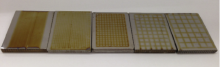
The LGN process was performed using a 100 W CW fiber laser (SP-100C-0013, SPI and A& P Co., Ltd) with a wavelength of 1091 nm. The samples were positioned in a chamber, which was continuously purged with pure nitrogen gas at a rate of 40 L/min to create a nitrogen atmosphere during LGN. The flow rate of nitrogen gas was controlled by flow meters from two nozzles, one being the axial nozzle and the other for the chamber. The gas flow rate of axial nozzle was set at appropriate values to minimize plasma formation and in-drag of oxygen. The laser power was set at 90 W for the LGN. To select parameters for nitriding without melting, the laser spot diameter was varied from 0.5 mm to 2.2 mm, and the laser scanning speed was varied from 60 mm/min to 1500 mm/min. After selecting the suitable parameters for nitriding, nitride tracks were fabricated on the sample surface to form a network of grids having different fractions of nitride coverage, as shown in Fig. 1.
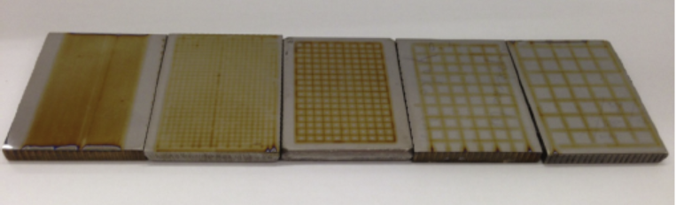 | Fig. 1. Grid-nitrided NiTi with different fractions of nitride coverage. |
Optical microscopy (OM, Leica DM4000M) was used for preliminary observation of the surface morphology of the laser-treated samples. Cross-section of laser tracks on the samples was studied using scanning-electron microscope (SEM, JEOL Model JSM-6490). The phases present in the nitrided and untreated NiTi samples were identified using X-ray diffraction (XRD, Rigaku SmartLab) at 40 kV and 40 mA using CuKα radiation for the 2θ ranging from 30° to 80° .
The surface roughness Ra of laser-nitrided and untreated samples was measured using a surface profilometer (Talysurf Series 2). To study the wetting behavior of the samples, measurement of contact angle of Hanks’ solution (a simulated body fluid with composition shown in Table 1) on the samples was performed[15]. The samples were cleaned with ethanol bath ultrasonically for 5 min and then dried thoroughly in cool air before measurement. A microsyringe was used to deliver droplets of Hanks’ solution onto the sample surface (5 µ l/droplet). By using an optical meter equipped with CCD video camera, the images were captured and studied using an image processing software (contact angle goniometer Sindatek Model 100SB).
| Table 1. Composition of Hanks’ solution (g/l) |
As the nitride layer was only around 1 to 2 µ m in thickness, nanoindentation tests employing a diamond Berkovich indenter were performed on untreated and nitrided NiTi (Hysitron nanomechanical test instrument, HLS1 module). Loading and unloading curves were acquired, and the hardness HN and reduced Young's modulus Er were determined from the curves. Five duplicates of each type of samples were used for calculating the mean values and errors.
The acetabular cup and the tibial plateau in human joint replacement are usually made of ultra-high-molecular-weight polyethylene (UHMWPE)[21], and titanium or titanium alloys are recommended materials for the femoral components[22]. Recent studies on the tribological behavior of titanium alloys against UHMWPE have been reported[23, 24], which indicated that the long-term performance of UHMWPE in the wear pair is a major factor for the life of total hip prostheses[25]. Consequently, reciprocating wear test was employed to evaluate the wear properties of grid-nitrided and untreated NiTi samples against UHMWPE. Linearly reciprocating pin-on-plate sliding test was performed (TE99 Universal Wear Machine, Phoenix Tribology). A flat-ended UHMWPE pin of 8 mm in diameter was fixed in the sliding carriage clamped and pressed endwise against the counterface plate, which was the NiTi sample. The diameter of the UHMWPE pin was chosen so that it was always in contact with both the nitrided and untreated surface. The reciprocating pin-on-plate sliding test was carried out at a normal load of 96 N, a frequency of 2 Hz, and of stroke length 30 mm, for test duration of 172, 800 cycles (about 10 km of sliding distance) in Hanks’ solution, which is a simulated body fluid. The wear resistance was evaluated using the wear factor (= wear volume (mm3)/load (N) × distance traveled (m)) for comparison of wear rates of different samples. For each type of samples, 5 duplicates were tested and the mean value together with the errors was calculated.
When the surface of the NiTi substrate is irradiated with a laser beam, part of the laser energy is absorbed by the substrate and the temperature of the surface rises. In a nitrogen atmosphere, TiN is formed due to the great affinity of Ti for nitrogen. Depending on the amount of laser power density absorbed, the surface may or may not melt. Thus to achieve nitriding without surface melting, the laser processing parameters, including laser power (P), laser spot diameter (d) and laser scanning speed (v), have to be carefully selected. In the present investigation, the laser power was fixed and the spot diameter and scanning speed were varied to efficiently fabricate TiN tracks without surface melting. To achieve this goal, the feasible processing parameters identified are laser power P = 90 W, scanning speed v = 60 mm/min and spot diameter d = 2.2 mm, with nitrogen flow rate at 40 L/min, the laser fluence being 40.9 J/mm2 under this set of parameters. Laser nitrided tracks with different separations were then fabricated on the sample surface to form networks of grids with different areas of nitride coverage (Fig. 1).
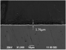
After LGN the sample surface shows a golden color, which suggests the formation of TiN. The cross-sectional SEM micrograph of a typical non-melted nitride track is shown in Fig. 2. A uniform layer of thickness of around 1.76 µ m could be clearly observed. TiN dendrites and heat-affected zones are absent due to the low laser fluence in the solid-state nitriding, which aims at producing TiN coating without changing the surface roughness of the NiTi samples.
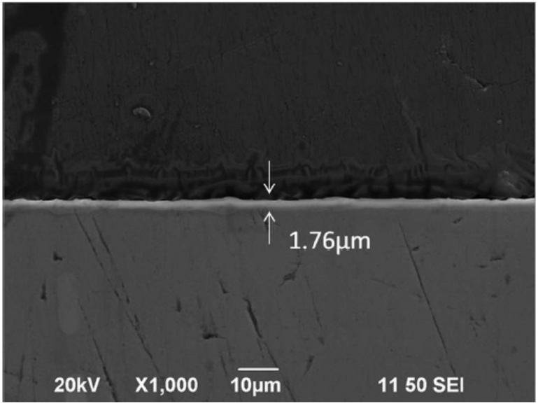 | Fig. 2. SEM cross-sectional view of a non-melted nitride track. |
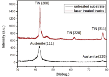
The X-ray diffraction patterns for the untreated and laser treated tracks are shown in Fig. 3. TiN peaks are present in the patterns for the laser treated tracks, evidencing the formation of a thin TiN layer on the NiTi. These peaks correspond to cubic titanium nitride (TiN) at (200) and (310). On the untreated NiTi sample only the austenite phase (also known as the B-2 phase or the FCC phase) is present (Fig. 3).
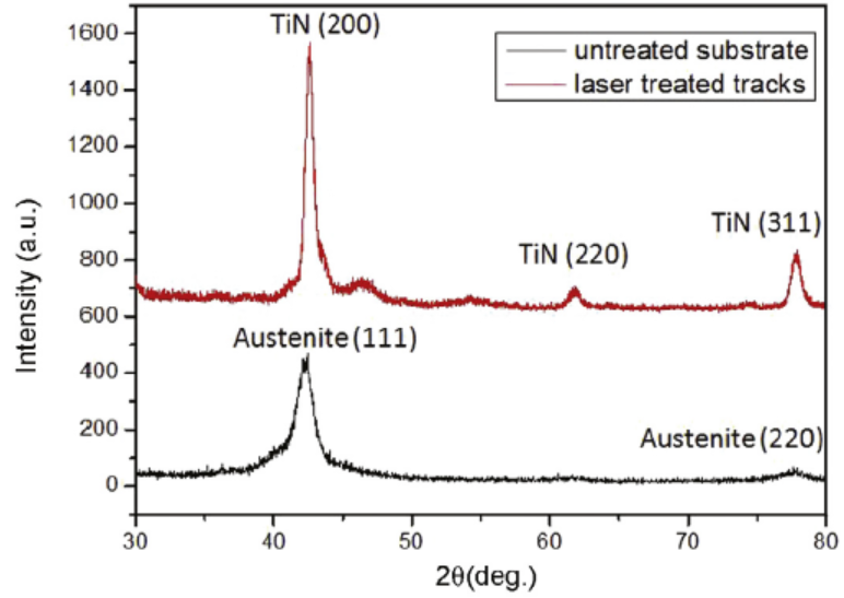 | Fig. 3. XRD patterns of the untreated substrate and laser treated tracks. |
The formation of the nitrided layer on a titanium alloy is more complicated than on pure Ti. Nitrogen (N) absorbed at the surface under laser irradiation diffuses inward into NiTi at elevated temperatures. Rapid diffusion of N into the surface of NiTi during laser treatment will first form an interstitial solution in NiTi. Upon saturation of this interstitial solution, TiN will eventually be formed due to the great affinity of Ti for N[26]. When TiN is formed on the surface NiTi by consuming Ti from the substrate, a Ni-rich phase will be formed somewhere, due to conservation of matter. According to a recent study on nitriding of Ti-6Al-4V by Morgiel and Wierzchon[27], Al was “ pushed out” to beneath the TiN layer. In fact, XPS (X-ray photoelectron spectroscopy) study of the surface layer of laser gas nitrided NiTi in one of our previous publications[28] clearly shows that Ni was absent in the nitrided layer of NiTi, similar to the “ pushing out” of Al in Ref.[27]. This “ pushing out” of Ni to beneath the surface layer was also reported in thermal oxidation of NiTi by Firstov et al.[29].
The results of these studies indicate depletion of Ni in the surface layer after nitriding or oxidation of NiTi. In agreement with these results, a number of studies[28, 30] also reported significantly reduced Ni ion release rate for NiTi nitrided by different processes, including laser gas nitriding by our group[28].
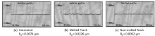
The topography and roughness of the surface layer after LGN depend strongly on the laser processing parameters, i.e., the laser fluence. To investigate changes in surface roughness, 2-D surface profiles were acquired using a surface profilometer (Talysurf Series 2). Typical surface profiles of untreated NiTi sample, nitrided NiTi samples with and without surface melting are shown in Fig. 4. The surface roughness Ra was significantly increased from 0.0074 µ m (untreated) to 0.0226 µ m (surface melting). The large difference in the surface roughness is attributed to surface melting and subsequent solidification during conventional LGN with high heat input and slow cooling rate[31]. Nitrogen atoms react with the melt pool to form a thick TiN layer, which has a relatively large roughness. On the contrary, the surface roughness of the substrate, which was nitrided without melting is almost the same as that of the untreated sample. This result is in agreement with the findings of a pervious study[32]. Post surface treatment like polishing is thus not needed and this is an important advantage of solid-state nitriding as compared with conventional nitriding involving melting.
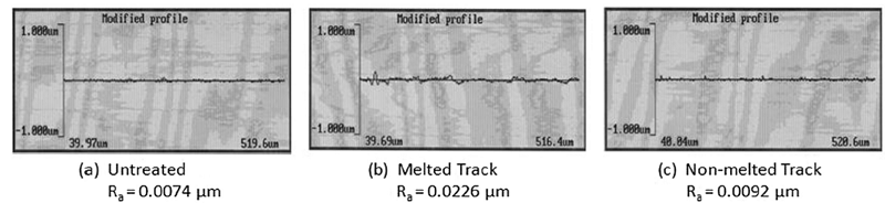 | Fig. 4. Surface profile of the (a) untreated sample, (b) melted track and (c) non-melted track. |
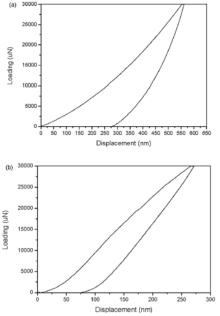
Nanoindentation test is commonly used to determine the mechanical properties of thin film due to its capability of continuously applying a small load. The resulting indentation depth is small so that substrate effect can be significantly reduced[33]. Moreover, the instrumented loading and unloading allows continuous capturing of the load-displacement curves, and from these curves important mechanical properties like the reduced Young's modulus Er and the hardness HN can be obtained[34]. Although the substrate effect can be greatly reduced using a very small load, surface roughness effect sets a restriction on the load, which cannot be too small, otherwise the nanoindentation curves would become very noisy. Thus an appropriate loading force and the corresponding indentation depth should be selected. In the present study the load selected was 50, 000 µ N, and the corresponding indentation depth for the nitride layer was around 450 nm, which is about 25% of the nitride layer thickness. This loading is an optimal selection as it resulted in a smooth load-displacement curve while the indentation depth is acceptably small. Fig. 5 shows typical nanoindentation curves for the NiTi substrate and the TiN coating. The hardness HN and reduced Young's modulus Er were extracted from the load-displacement curves. The nitride layer coating exhibits much higher values in hardness HN (17.92 ± 3.69 GPa) and reduced Young's modulus Er (131.65 ± 8.04 GPa) than the NiTi substrate (HN of 4.44 ± 0.55 GPa and Er of 66.28 ± 2.54 GPa). The hardness and reduced Young's modulus of the nitride layer are about 4 times and 2 times of untreated NiTi, respectively. The ratio of hardness to reduced Young modulus has been proposed as an important factor in determining wear resistance [35]. By comparing the nitride layer and the NiTi substrate, the HN/Er ratio of NiTi substrate (0.066) is about half that of the nitride layer (0.136). The higher value of HN/Er ratio of the nitride layer is in agreement with the results of Cheng and Zheng [36].
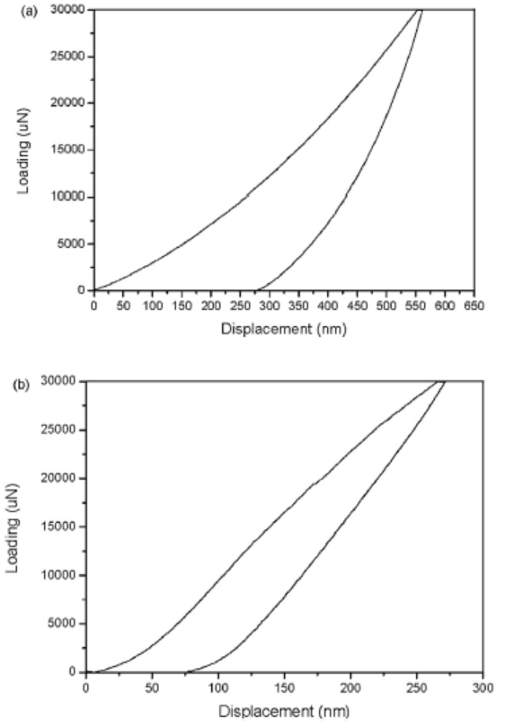 | Fig. 5. Typical nanoindentation curves of (a) untreated NiTi and (b) nitride track. |
Fig. 6 shows the wettability results for the untreated NiTi and nitrided NiTi in Hanks’ solution. As shown in Fig. 6, the liquid droplet on the surface of nitrided NiTi has a contact angle of 62.34° ± 2.74° , which is smaller than that on untreated NiTi (67.06° ± 2.26° ). This indicates that nitrided NiTi is more hydrophilic. In the paper by Borruto et al.[37], it was pointed out that the wetting behaviors of the contacting surfaces in a tribological pair would significantly affect the wear behavior of the pair. It was concluded there that a hydrophilic-hydrophobic coupling enhances the efficiency of lubrication due to the presence of pressed water film between the pair. This film results in low wear rate and low friction coefficient in the tribological system. As UHMWPE is hydrophobic, the better hydrophilicity of the nitrided NiTi in Hanks’ solution would enhance lubrication and reduce friction and wear between nitrided NiTi and UHMWPE.
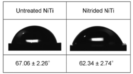 | Fig. 6. Images of contact angles of Hanks’ solution droplet resting on the surface of treated and untreated NiTi. |
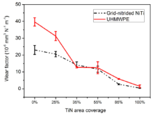
To study the effect of grid-nitriding on wear performance, reciprocating wear tests between UHMWPE and NiTi samples were performed in Hanks’ solution. The wear resistance is evaluated by using the wear factor, which is the wear volume per unit normal load per unit sliding distance, and is a parameter commonly used in the biomaterials community[38]. A higher wear factor indicates more serious wear damage and hence lowers wear resistance. Fig. 7 shows the wear factor of UHMWPE, untreated and various grid-nitrided NiTi samples after 172, 800 cycles in the test, based on the results of 5 duplicate pairs. The small error bars in Fig. 7 indicate that the wear test results are acceptably reliable.
 | Fig. 7. Wear factor of grid-nitrided NiTi against UHMWPE in Hanks’ solution. |
The wear test results demonstrate that grid-nitrided NiTi exhibits better wear performance than that of untreated NiTi in the wear pair. It is clearly seen that the wear rates for both NiTi and UHMWPE were significantly reduced in the nitrided-NiTi/UHMWPE pair.
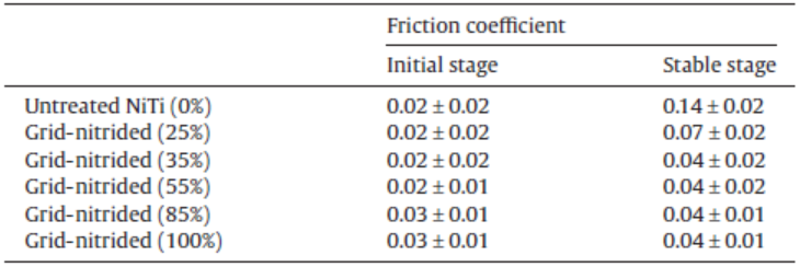
The friction coefficient between UHMWPE and the NiTi counterparts in the reciprocating wear tests is summarized in Table 2. Obviously, the friction coefficient for grid-nitrided NiTi is lower than that for untreated NiTi.
| Table 2. Coefficient of friction of UHMWPE in reciprocating sliding test |
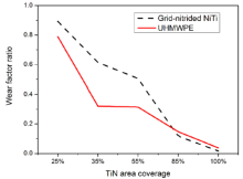
The wear factor ratio of the nitrided-NiTi/UHMWPE pair compared with bare-NiTi/UHMWPE pair for different percentages of TiN area coverage is shown in Fig. 8. It indicates that as the TiN area coverage increases, the wear volume losses of TiN and UHMWPE both decrease. However, when the TiN area coverage increases from 35% to 55%, the wear factor ratio of TiN and UHMWPE is nearly the same. Going beyond 55% TiN area coverage, the wear factor ratio drops again in both of TiN and UHMWPE. TiN is much higher in hardness than NiTi and has a higher wear resistance. Thus increasing the area of coverage by TiN favors wear performance. On the other hand, the grooves in the network provide room for wear debris formed, which would otherwise stay on the surface and become detrimental to friction and wear as a third body.
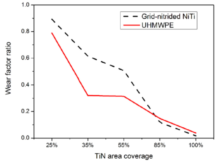 | Fig. 8. Wear factor ratio of the nitrided-NiTi/UHMWPE pair compared with that of bare-NiTi/UHMWPE pair for different percentages of TiN area coverage. |
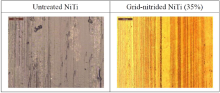
Stereoscopic optical morphology of the surface of UHMWPE pin before and after the wear test is shown in Fig. 9. It can be observed that the machined pattern on the UHMWPE pin against untreated NiTi has totally disappeared while that on the pin against grid-nitrided NiTi is still visible, indicating a lower wear rate of the UHMWPE pin in the latter case. Fig. 10 shows the appearance of NiTi after the wear test. UHMWPE transferred layers were formed on the untreated NiTi plate surface. It was associated with a relatively high coefficient of friction of untreated NiTi sample. On the other hand, there is no UHMWPE transferred layer formed on the grid-nitrided NiTi. The above experimental results indicate that the grid-nitrided NiTi/UHMWPE pair exhibits much better wear performance than that consisting of untreated NiTi and UHMWPE.
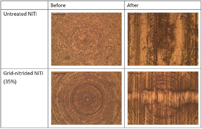 | Fig. 9. Optical images of the surface of UHMWPE pin against untreated NiTi and grid-nitrided NiTi (35%). |
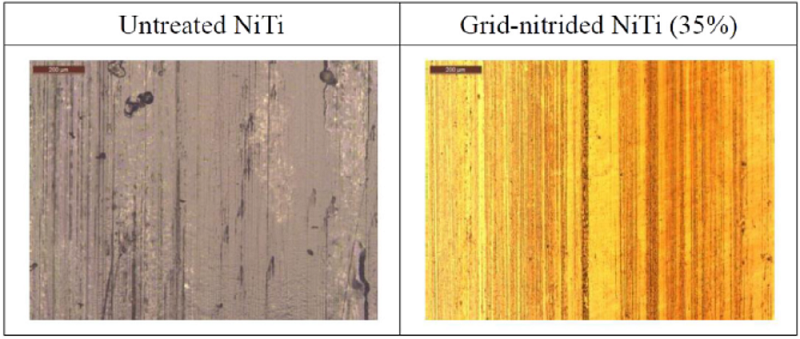 | Fig. 10. Optical images of the surface of untreated NiTi and nitrided NiTi. |
(1)With the laser power and nitrogen gas flow rate fixed at 90 W and 40 L/min, the optimal laser scanning speed and laser spot diameter are respectively 60 mm/min and 2.2 mm for achieving solid-state nitriding. The thickness of nitride layer is about 1.76 µ m.
(2)Nitriding of NiTi improves the wear performance of the NiTi/UHMWPE wear pair in Hanks’ solution, as evidenced by the significant reduction in wear rates for both contact materials in the pair. This could be attributed to a higher HN/Er ratio of the nitride layer and to a lower coefficient of friction. In addition, the wear factors decrease with increasing area of nitride coverage.
(3)Nitriding of NiTi increases its hydrophilicity in Hanks’ solution. A hydrophilic (nitrided NiTi)/hydrophobic (UHMWPE) friction couple promotes the efficiency of lubrication and further reduces the wear rate.
(4)The results of the present investigation indicate that laser grid-nitriding of NiTi via solid-state diffusion is an effective process for improving the tribological performance of the NiTi/UHMWPE wear pair in Hanks’ solution.
This work was supported by the Research Grants Council of the Hong Kong Special Administrative Region, China (Project No. PolyU 524210E).
The authors have declared that no competing interests exist.
| [1] |
|
| [2] |
|
| [3] |
|
| [4] |
|
| [5] |
|
| [6] |
|
| [7] |
|
| [8] |
|
| [9] |
|
| [10] |
|
| [11] |
|
| [12] |
|
| [13] |
|
| [14] |
|
| [15] |
|
| [16] |
|
| [17] |
|
| [18] |
|
| [19] |
|
| [20] |
|
| [21] |
|
| [22] |
|
| [23] |
|
| [24] |
|
| [25] |
|
| [26] |
|
| [27] |
|
| [28] |
|
| [29] |
|
| [30] |
|
| [31] |
|
| [32] |
|
| [33] |
|
| [34] |
|
| [35] |
|
| [36] |
|
| [37] |
|
| [38] |
|