

Influence of Processing Conditions on Microstructure and Mechanical Properties of Large Thin-Wall Centrifugal Ti-6Al-4V Casting
Cite this Article
Xin Feng, Jianke Qiu, Yingjie Ma, Jiafeng Lei, Yuyou Cui, Xinhua Wu, Rui Yang. Influence of Processing Conditions on Microstructure and Mechanical Properties of Large Thin-Wall Centrifugal Ti-6Al-4V Casting. Journal of Materials Science & Technology, 2016, 32(4): 362-371 
Permissions
Copyright reserved, Editorial board of Journal of Materials Science & Technology
Influence of Processing Conditions on Microstructure and Mechanical Properties of Large Thin-Wall Centrifugal Ti-6Al-4V Casting
Abstract
In this work, the effects of mould pre-heating temperatures and hot isostatic pressing (HIPping) process on the microstructural characteristics and mechanical properties, including static tensile and damage-tolerance properties of large thin-wall cylindrical Ti-6Al-4V casting, have been studied. The experimental results show that with the increasing mould pre-heating temperature from 673 to 873 K, the casting microstructures change from a mixture of Widmanstätten and colony microstructure to a primary colony. The centre of the thick wall section has relatively coarse microstructure than the edge and thin section. Lower mould pre-heating temperature brings about more porosities. HIPping process, which not only reduces the casting pores effectively but also increases the prior β grain boundary cohesion and coarsens the microstructure, is essential to improving the ductility of the casting. Due to the oxygen contamination and finer microstructure on the surface, micro-hardness profiles on the cross section present a decreasing tendency from the surface to inner. The thickness of the reaction layers for the different mould pre-heating temperatures is nearly the same (~450 µm). On the whole, the tensile strength and micro-hardness decrease with increasing mould pre-heating temperature from 673 to 873 K. However, the fracture toughness and fatigue crack growth resistance of the castings increase with increasing mould pre-heating temperature.
Keyword:
Ti-6Al-4V alloy; Centrifugal investment casting; Hot isostatic pressing; Casting microstructure; Tensile properties; Damage-tolerance properties
1. Introduction
Titanium alloys have been widely used in the aeronautical and aerospace industries due to the weight reduction, corrosion resistance, elevated and cryogenic temperature applications and volume constraints, such as the typical use presented by Boyer[1]. However, the application of titanium alloys is still limited by their high cost, including material and manufacture costs. Casting technology is one of the competitive technologies for reducing manufacture cost[2, 3 , 4]. In recent years, the centrifugal casting for titanium alloys has been developed because of the good fluidity under the centrifugal force, which increases the casting precision and quality. Still, castings have inferior mechanical properties compared with forgings because of the inherent coarse microstructures and inevitable defects (e.g., porosities/shrinkage cavities), which are generated due to the solidification from the melting point with a relatively high cooling rate. After the introduction of hot isostatic pressing (HIPping) process for the castings, the internal porosities/cavities can be mostly closed and the quality can be further improved, which makes the application of titanium alloy castings in the industries into reality[5]. Furthermore, there are some measures to optimize the casting microstructures and tailor the mechanical properties, such as changing the chemical composition (e.g., the addition of B[6 , 7]), casting processing[2, 3] and subsequent heat treatments[8 , 9]. The adjustable variables in the casting process mainly include mould material, mould pre-heating temperature, pouring temperature, post-solidification cooling rate and rotational velocity. In this study, the effect of mould pre-heating temperature on the castings was investigated. To ensure the success and quality of the casting, the mould material should be pre-heated to a proper temperature. However, too high or too low pre-heating temperature would result in adverse consequences. Too high pre-heating temperature would aggravate the metal-mould interface reaction and lead to overlarge casting microstructures. Too low pre-heating temperature would decrease the molten metal flow[10], and thus could not ensure a complete fill for the mould cavity of the large thin-wall centrifugal casting, even though the mould reaction could be effectively limited at lower temperatures (e.g., lower than 473 K). Therefore, an appropriate temperature range should be chosen (i.e., 673, 773 and 873 K) to conduct a comparative study about the influence of mould pre-heating temperatures.
In the aviation and aerospace field, the design criteria of structural components have been changed from the static strength design to damage-tolerance design to satisfy the requirement of safe services[11]. Thus, the high-quality structural materials should have high strength, high fracture toughness and low fatigue crack growth (FCG) rate. Ti-6Al-4V alloy, as a workhorse in titanium alloys, has been widely applied in the aerospace industry with different product forms[1]. In recent years, the casting products have become topics of great interest, in particular for the investment casting, which reduced the part count and manufacturing expense[3]. The thin-walled Ti-6Al-4V casting cases have been produced with the centrifugal investment casting under the financial support of the COLTS program. However, the effect of casting processing conditions, especially for mould pre-heating temperature, on the microstructures and mechanical properties of the real workpiece has been rarely investigated, and few documents reported large scale thin-walled titanium alloy castings, which are widely demanded in aerospace. Therefore, this work aimed to study the relationship between processing conditions and microstructural characteristics and mechanical properties, including tensile properties and damage-tolerance properties, to further optimize the microstructures and properties of centrifugal investment castings of Ti-6Al-4V alloy.
2. Materials and Experiments
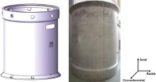
The investigated samples were extracted from the large thin-wall Ti-6Al-4V casting cases, which were produced by centrifugal investment casting process. The large thin-wall vertical cylinders, as shown in Fig. 1, are with a diameter of 600 mm, height of 750 mm and two thicknesses of 4 mm (thin section, the part of cylinder body) and 19 mm (thick section), respectively. Melting process was performed in a cold-wall crucible, before the molten liquid metal was poured into thin walled cavities. The cavity mould should be preheated to a certain temperature for ensuring the success of the casting and obtaining a relatively homogeneous microstructure. The rotational velocity used in the vertical centrifugal casting was 200 r/min, which could ensure a complete fill for the mould cavity. The rotational direction was anticlockwise. In this investigation, three mould pre-heating temperatures, i.e., 673, 773 and 873 K, respectively, were conducted for a comparative study, which produced three types of thin-wall titanium alloy castings. Furthermore, the as-cast and HIPped microstructures have also been compared to ascertain the specific influence of HIP process on the mechanical properties of castings. The HIPping process adopted in this study was 1203 K/1.5 h/130 MPa and finished with furnace cooling to 473 K.
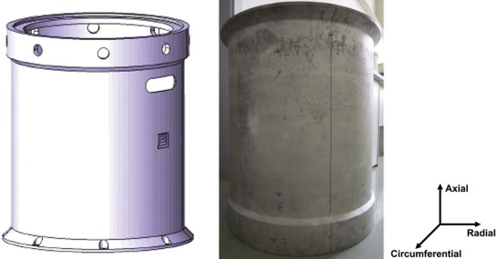 | Fig. 1. Defined space component (left) and the initial cylindrical Ti-6Al-4V casting (right). The overall dimension is 600 mm in diameter and 750 mm in height, and the wall thickness is 4 mm in thin section and 19 mm in thick section. The coordinate system has been attached. |
In this study, microstructure characterization, micro-hardness, room temperature tensile, fracture toughness and FCG rates testing were conducted for these three castings before and after HIPping, respectively, and the influence from the different positions of the same cylinder casting, which corresponded to the different cooling rates, were also analyzed. Finally, the effect of mould pre-heating temperatures, casting thickness and HIPping process on the microstructural characteristics and mechanical properties has been summarized.
Microstructure characterization was carried out by optical microscopy (OM, Zeiss-Axiover 200MAT). Micro-hardness (Vickers-hardness, with a loading of 200 gf and dwell time of 10 s) data were obtained on the section from the outside surface to the inner of these casting specimens. Flat plate tensile specimens (thickness: 3 mm, gauge width: 4.0 mm and gauge length: 20 mm) were extracted from the thin section of the castings. The tensile direction was along the axial direction of the casting, as indicated in Fig. 1. Fracture toughness at ambient temperature was measured using compact-tension (CT) specimens with a size of 7.5 mm in thickness and 30 mm in width. FCG resistance at ambient temperature in air was tested on the CT specimens with a size of 3.0 mm in thickness and 30 mm in width. The fatigue waveform was a sinusoidal wave form with a frequency of 10 Hz and an R ratio of 0.1. After testing, FCG specimens were mechanically polished and etched by Kroll's reagent to reveal the microstructure along the FCG path. The fatigue failure mechanism has been further analyzed with the aid of transmission electron microscopy (TEM) and electron back-scattering diffraction (EBSD) technique. The fracture surfaces were also observed and compared by scanning electron microscopy (SEM).
3. Results and Discussion
3.1. Microstructural characteristics
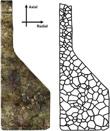
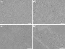
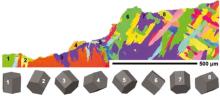
Firstly, the macrostructure on the longitudinal section, stretching from the thick section (19 mm) to thin section (4 mm), of the cylindrical casting has been analyzed, as shown in Fig. 2. The outlined prior β grain morphology shows that, for both thick and thin section, the edge part tended to have a columnar prior β grain morphology and the centre part tended to have an equiaxed morphology. The grain morphology is controlled primarily by the local thermal conditions[2]. During the solidification of the liquid metal in the thin walled cavities, the direction of heat flow was from the centre to the edge. On the mould-metal interface, the β grain firstly nucleated and then grew along the negative direction of the heat flow. In the centre part, a homogeneous nucleation and growth of β grains occurred. Besides the β grain morphology, it was also found that the β grains in thick section are overall larger than those in thin section, and the maximum prior β grain size is about 3.5 mm in diameter. Meanwhile, the fine-scale microstructure varies with both the location and section size, as shown in Fig. 3. Compared with the thin section, thick section has larger α /β colonies. And the centre part has larger α /β colonies than the edge part. The fine-scale microstructural morphology is controlled primarily by the post-solidification cooling rate.
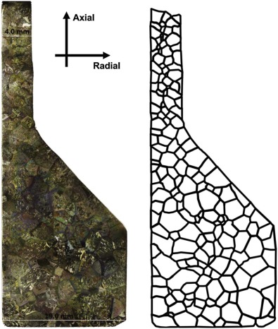 | Fig. 2. Micrographs showing the macrostructure on the longitudinal section, stretching from the thick section (19 mm) to thin section (4 mm), of the cylindrical casting with a mould pre-heating temperature of 873 K and after HIPping. OM image (left) and the outlined prior β grain morphology (right). |
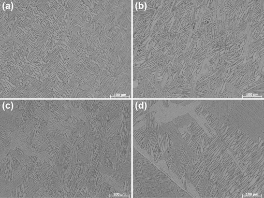 | Fig. 3. OM images showing the microstructures at different locations of the macrograph in Fig. 2: (a) edge of thin section, (b) centre of thin section, (c) edge of thick section, (d) centre of thick section. |
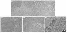
In addition to the local microstructural inhomogeneity, mould pre-heating temperatures and HIPping process also affect the microstructural characteristics, as shown in Fig. 4 (Note: the casting with mould pre-heating temperature of 873 K was not cut in half before HIPping process). For the pre-heating temperature of 673 K, the casting consists of a mixture of Widmanstä tten and colony microstructure. With increasing pre-heating temperature, the casting is consisted primarily of colony α microstructure. By comparing these three casting microstructures, it is shown that the structural unit size increases with increasing the mould pre-heating temperature. The lower mould pre-heating temperature brought about relatively higher cooling rate, thus giving rise to a much finer microstructure. The major effects of HIPping process on the casting microstructure are the removal of porosities and promotion of grain growth[5]. After the HIPping process, as shown in Fig. 4, both α /β colonies and α laths became coarsened due to the combined effect of the high pressure and temperature. The condition at lowest preheating temperature was the most obvious. The mould pre-heating temperature also affects the casting defects, especially for the porosities, as shown in Fig. 5. With increasing the mould pre-heating temperature, the number of porosities decreases dramatically. Under the casting condition with low mould pre-heating temperature, the solidifying time of the casting is short. Entrapped gas could not be expelled before the thin walled casting is solidified, so there are more casting pores in the casting[12].
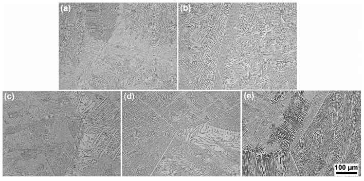 | Fig. 4. OM images showing the effects of mould pre-heating temperatures and HIPping process on the casting microstructures: (a) 673 K, (b) 673 K + HIP, (c) 773 K, (d) 773 K + HIP, (e) 873 K + HIP. |
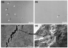
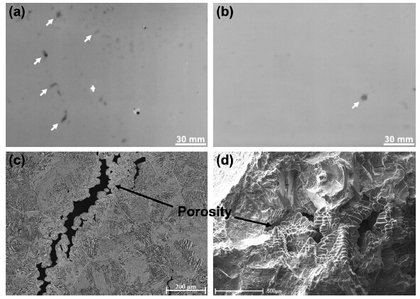 | Fig. 5. X-ray detection showing the variation of casting defects with the mould pre-heating temperatures: (a) 673 K, (b) 773 K. The dark spots represent the casting porosities, as indicated by white arrows. The casting porosities from 773 K have been presented with (c) OM image from the cross section and (d) SEM image from the tensile fracture. |
Factors influencing the casting microstructure mainly include the chemical composition, pouring temperature and cooling rate during and after solidification. The chemical composition and the pouring temperature are the same for all the castings in the present study. The cooling rate of the investment castings depends on the heat transfer between the mould material and casting metal, which is related to the heat transfer coefficient and heat capacity of mould materials, possible reaction with mould materials, mould pre-heating temperature and wall thickness of the casting. In this study, obviously, the last two factors determine the microstructural characteristics. In thin section, the heat could be transferred to the mould more quickly than that in thick section. Thus the cooling rate in thin section is higher than that in thick section. The grain size obtained during solidification is determined by the competition between the nucleation and growth rates. With increasing cooling rate, the nucleation ratio increases. But the diffusion rate decreases, so the new phases have difficulty in growing. The combined effect of the increase in nucleation ratio and decrease in growth rate results in smaller grain size[3].
3.2. Tensile properties
The tensile properties of the Ti-6Al-4V castings are listed in Table 1. By comparing these five different processing conditions, it can be found that, for the as-cast condition, both the tensile strength and elongation of the casting with the mould pre-heating temperature of 773 K are higher than those at 673 K. However, for the condition after HIPping, an inverse situation emerges. With increasing mould pre-heating temperatures, both the tensile strength and elongation of post-HIPped castings decrease.
| Table 1 Tensile properties of the thin sections from the cylindrical castings produced under different processing conditions (average of three test specimens) |
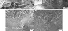
To clarify the variation of tensile properties as stated above, the fracture surfaces of the tensile specimens were carefully examined and compared with the aid of SEM, taking the casting of 673 K before and after HIPping as the example, which is shown in Fig. 6. Obviously, there are two distinct fracture surfaces. For the as-cast sample, the failure is typically dominated by the intergranular cleavage fracture where most of the decohesion appear at prior β grain boundary, and cast pores can be easily found on the fracture surface, as indicated in Fig. 6(c). But for the post-HIPped sample, it is a typical ductile fracture and associated with more dimples and mostly inter-colony decohesion. On the whole, the fracture surface of post-HIPped sample is relatively flatter than that of the as-cast. The variation of fracture features before and after HIPping process directly explains the increase of tensile strength and elongation after HIPping at 673 K. Specifically, the HIPping process remarkably eliminates the cast pores and improves the cohesive strength of β grain boundary. With increasing the mould pre-heating temperature from 673 to 773 K, both the strength and ductility of the as-cast sample are increased. This is mainly because the higher pre-heating mould temperature would decrease the solidification rate and thus reduce the presence of cast pores, as shown in Fig. 5. Although the higher mould temperature would produce the relatively coarser microstructure and decrease the strength, it played a secondary role while comparing with the positive effect of the elimination of cast pores. On the improvement of the tensile performance, HIPping process had a more obvious effect for the lower pre-heating temperature case, because the number and size of micro-pores would become much smaller in the castings with increasing mould pre-heating temperature.
 | Fig. 6. Comparison of the SEM tensile fractographs of the casting with mould pre-heating temperature of 673 K before and after the HIPping processing: (a, c) as-cast, (b, d) post-HIPped. |
For the post-HIPped samples, the strength and ductility have a decreasing tendency with the increase of mould pre-heating temperatures due to the microstructure coarsening. For the lower pre-heating temperatures, the casting microstructure is much finer, as shown in Fig. 4. The finer microstructural size of Ti-6Al-4V alloy castings increases both the grain and phase boundaries, and then results in the higher strength and ductility, which can be explained by the Hall-Petch mechanism. This viewpoint is also supported by the observation that the strength tends to increase as the colony size decreases[8, 13 , 14].
3.3. Micro-hardness
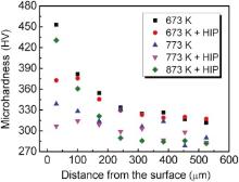
The directionality of heat transfer and non-uniformity of cooling during the casting process of thin-wall products determine the inhomogeneous microstructures and properties in the whole cross section. Fig. 7 shows the variation of the Vickers micro-hardness from surface to inner under five processing conditions. In most cases, the micro-hardness reduces rapidly from the surface to a depth of 240 µ m and then reduces slowly to a depth of 450 µ m. When the depth is more than 450 µ m, the micro-hardness tended to be a constant. Thus, the thickness of the reaction layers is about 450 µ m for the mould in this study. The variation tendency of the micro-hardness and the thickness of the reaction layer are almost the same for the investigated five processing conditions. It can also be seen that, on the whole, the micro-hardness decreases with the increase of mould pre-heating temperature. The casting microstructure obtained at the mould pre-heating temperature of 673 K has the highest Vickers micro-hardness.
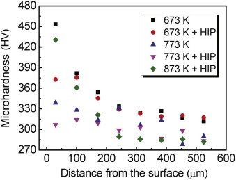 | Fig. 7. Micro-hardness profiles near the surfaces of the thin sections of the cylindrical castings produced by different processing conditions. |
The reason for the variation of micro-hardness stated above can be attributed to two aspects. First, the cooling rate during the solidification presents a descending change from the surface to the inner of castings. So, the microstructure has a corresponding variation from fine to coarse. The Vickers hardness decreases with the increase of microstructure size. The smaller microstructure produces higher grain and phase boundary density and thus higher Vickers hardness. The higher mould pre-heating temperature also corresponds to lower cooling rate and coarser casting microstructure. Second, the surface hardening layer is caused by the oxygen contamination[3].
3.4. Fracture toughness
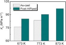
To satisfy the requirement of the application in aerospace field, the damage-tolerance properties of the Ti-6Al-4V cylinder casting, including fracture toughness and FCG, have been evaluated in this and in the next section, respectively. Because the thicknesses of the extracted CT samples, which is restricted by the thickness of the casting wall, cannot satisfy the fracture toughness test standard for metals[15], the values of mode I fracture toughness, Kq, of the casting process under different processing conditions are shown in Fig. 8. It should be noted that the Kq values calculated on the basis of a plane strain concept are usually higher than KΙ C values. For the engineering application, however, the information given by the Kq values is still sufficient for the property evaluation and comparison, because they represent the force to trigger unstable crack propagation for the cylinder castings investigated here. As shown in Fig. 8, the fracture toughness of both the as-cast and post-HIPped Ti-6Al-4V castings increases with increasing mould pre-heating temperature. And the post-HIPped has higher Kq values than the as-cast. The most significant improvement in fracture toughness has been found for the casting at 673 K.
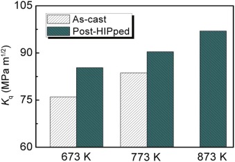 | Fig. 8. Fracture toughness (Kq) as a function of the processing conditions (average of three test specimens). |
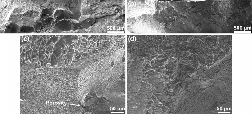
Fig. 9 shows the fracture surfaces of the as-cast and post-HIPped samples of 673 K after the fracture toughness tests. The fracture surface images indicate that the as-cast sample mainly fractured along prior β grain boundaries, which corresponds to the lower-energy crack paths and thus led to the lower fracture toughness. Grain boundaries, as the last solidification regions during the casting process, are usually the weakest positions in titanium castings and have micropores, as shown in Fig. 9(a). Micropores in the boundaries of prior β grains are apt to cause stress concentration and develop into a crack at the micropore tip. Once the cracks nucleated from micropores in the alloy, they will propagate along the weak boundaries under the imposed stress, which aggravate the failure of the material. The fracture mode transforms from the mixed intergranular and transgranular fracture to predominately transgranular fracture after the HIPping process. The transgranular fracture with large and elongated dimples, as shown in Fig. 9(b), is mainly inter-colony decohesion. Such a situation is similar to the tensile fractures, as shown in Fig. 6. Therefore, it can be concluded that macro- and micro-porosities are removed and grain boundary cohesion is enhanced by HIPping process[16], and then the fracture toughness of the casting microstructure will be remarkably improved.
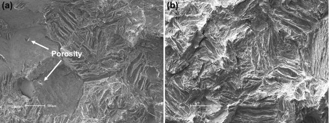 | Fig. 9. Comparison of the SEM fractographs of the casting with mould pre-heating temperature of 673 K after fracture toughness tests: (a) as-cast, (b) post-HIPped. |
Another variation is that the Kq values increases with increasing mould pre-heating temperatures. As we stated in Section 3.1, both the high mould temperatures and HIPping process will make the microstructure coarse. The coarser microstructures usually lead the more tortuous crack paths, which will consume more energy and increase the fracture toughness of the alloys.
3.5. FCG behaviour
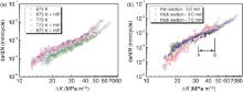
FCG rates (da/dN) as a function of applied stress intensity range (Δ K) for the cylindrical Ti-6Al-4V castings produced under different processing conditions are plotted in Fig. 10(a). The tested samples were extracted from the thin section and with a thickness of 3.0 mm. It shows that with increasing the mould pre-heating temperatures, the FCG rates decrease. And after the HIPping process, FCG rates also slightly decrease.
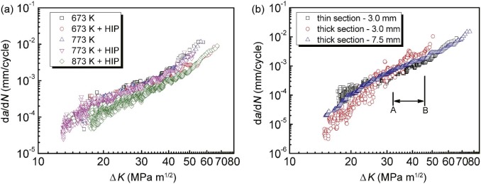 | Fig. 10. FCG rates (da/dN) as a function of applied stress intensity range (Δ K), tested under R = 0.1, for the cylindrical Ti-6Al-4V castings: (a) comparison of different processing conditions, (b) effect of sample location and thickness, which are conducted on the 873 K + HIP casting. |
As the solidification process and microstructure would be affected by the thickness of the cyclinder wall, some samples with different thickness from the thin and thick sections were employed to compare their FCG behaviour, as shown in Fig. 10(b). It shows that FCG data of 3.0 mm are more scattered than that of 7.5 mm for the thick section. The possible reason is that the sample from the thick section with a thickness of 3.0 mm contains few to less to least colonies in the sample thickness direction. While the crack propagate ahead, the encountered colonies have different crystallographic orientations (either favourably or unfavourably orientated for the crack growth), which will result in the considerable variation in FCG rates and then present a scattered distribution in the FCG rates[17]. Another feature is that the sample from the thin section and with a thickness of 3.0 mm has the similar FCG resistance with the sample from the thick section with a thickness of 7.5 mm. However, the sample from the thick section with a thickness of 3.0 mm has intersected with the above two FCG rate curves and can be divided into two stages, as indicated by the letter “ A” in Fig. 10(b). Before the point “ A” , the FCG rate is lower than that of the other two samples, and the opposite case appears after point “ A” . The reason for this situation is a combined effect of structural unit size, mainly the α /β colony, and sample size. The sample from the thick section has relatively lager α /β colonies. While the sample is 3.0 mm in thickness, the relatively large and few α /β colonies will result in the FCG path having higher levels of crack deflection and roughness-induced crack closure, and thus lower FCG rates. But for the sample with 7.5 mm, more α /β colonies existing in the thickness direction means more chances to change the propagation direction and finally exhibit relatively flatter FCG path on the whole. For the later stage of the investigated FCG regime of the sample with 3.0 mm, quasi-cleavage fracture of α /β colonies simultaneously occurs on the nearly whole thickness and almost constitutes one facet in thickness direction, as shown in Fig. 11, and results in the fast propagation.
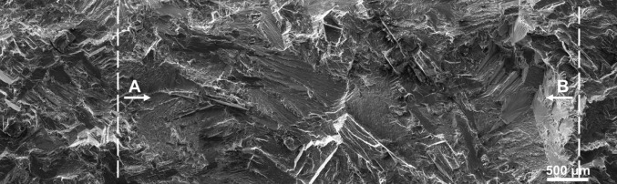 | Fig. 11. SEM image showing the FCG path of the sample with a thickness of 3.0 mm from the thick section of the 873 K + HIP casting. The regions, as indicated with “ A” and “ B” , correspond to the labels in Fig. 10(b). FCG direction is from left to right. |
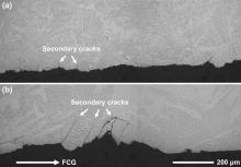
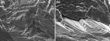
Fig. 12 shows the longitudinal section of the as-cast and post-HIPped samples after FCG tests along the fatigue crack path. It indicates that the post-HIPped sample has more crack branching, micro-cracking and deflection, and its crack path is more tortuous than that of the as-cast. In this study, the crack propagate forward mainly along a path perpendicular to the lamella long axis direction. And the quasi-cleavage of α /β colony along intense planar slip bands is the predominant failure mode[18]. The quasi-cleavage cracking observed on the longitudinal section can be further illustrated by the planar facets on the fracture surfaces, as shown in Fig. 13. Usually an α /β colony corresponds to a planar facet. The as-cast sample has much smaller colonies, which bring about the smaller facets. And the smaller facets on the different planes connect with each other, which constitute a relatively flatter fracture surface than the post-HIPped sample.
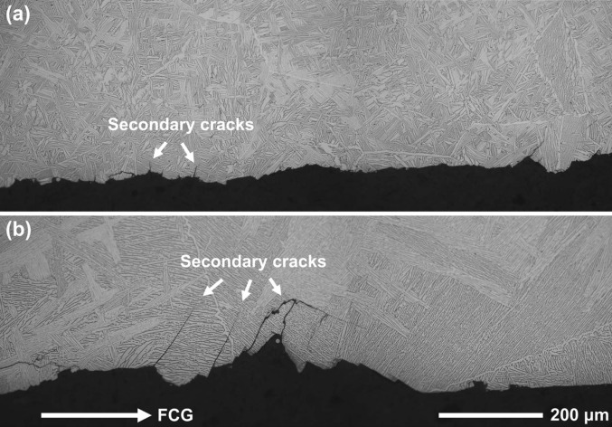 | Fig. 12. OM images showing the FCG path profiles of Ti-6Al-4V castings with different processing conditions: (a) 673 K, (b) 873 K + HIP. |
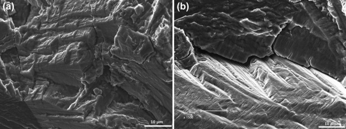 | Fig. 13. SEM fractographs of the FCG samples from the casting with a mould pre-heating temperature of 773 K: (a) as-cast, (b) post-HIPped. |
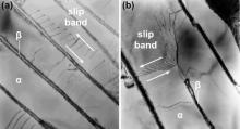
The planar facets on the fatigue fracture surface are related to the planar slip behaviour in α lamellae, as shown in Fig. 14. It shows that planar slip bands include those both parallel and perpendicular to the long axis direction of α lamellae. In titanium alloys, the priority order to start the slip systems is < a > prismatic, < a > basal and < c + a > pyramidal slip, which is determined by the corresponding critically resolved shear stress (CRSS) [19 , 20], and [0001] c-axis of α phase is quasi-parallel to the long axis direction of β platelets [18, 21 , 22]. It can be seen that, in this study, the fatigue dislocation activate along ( 

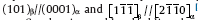
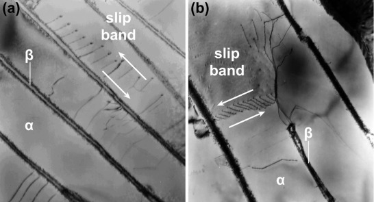 | Fig. 14. Bright-field TEM micrographs showing planar slip bands with respect to the α /β colony long axis direction: (a) parallel, (b) transverse. |
Taking one of the casting microstructures as an example, the EBSD technique was further utilized to characterize the relationship between the crystallographic orientation of α /β colonies and planar facets on the fracture surfaces, as shown in Fig. 15. Colonies 1, 2, 3, 6 and 7 are cracked on basal plane, and colonies 6 and 8 are cracked on prismatic plane. In colony 6, the fatigue crack propagation path has transformed from along the basal slip to along the prismatic slip. Although the probability of the occurrence of prismatic slip is relatively larger than that of basal slip, and grains orientated for prismatic slip have also been reported to act as crack initiation sites[25] and [26], the ultimately cracked planes for the current case mostly appeared on the basal plane, which coincide with the previous research[25, 27, 28].
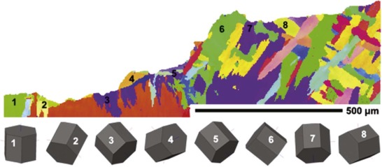 | Fig. 15. EBSD mapping showing the crystallographic orientation of α colonies near the FCG path. 3D crystal viewers have been presented for the corresponding labelled α colonies. |
However, there are still some colonies that did not crack along favourable slip orientation, such as colony 5. Bantounas et al.[27] explained this kind of phenomenon by assuming that all grains had active slip systems prior to cracking. The unfavourable orientated crack planes are believed to be influenced by prior cracking in neighbouring grains and are a consequence of accommodating crack propagation. For the cracks forming along favourable slip planes, once the crack propagated into a differently orientated neighbouring colony, the crack propagating direction would change into the slip band in the neighbouring colony. If the misorientation between two neighbouring colonies was large, there would be a larger deflection in the FCG path.
In conclusion, the larger α /β colony sizes and misorientation between two neighbouring colonies will cause larger tortuosity in the FCG path, which increase the crack closure degree and reduce the effective Δ K value, then decrease the crack growth rate da/dN. Thus, with increasing mould pre-heating temperatures from 673 to 873 K and after the HIPping process, the casting microstructure will become coarser and the crack path will have larger crack deflection, higher fracture surface roughness and consequently slower crack growth rate [29 , 30].
4. Conclusions
The effects of the mould pre-heating temperature and HIPping process on the microstructures and mechanical properties, including the static tensile and damage-tolerance properties, of the large thin-wall cylinder Ti-6Al-4V casting have been investigated. The following conclusions were made.
(1)The microstructure of the large thin-wall cylinder casting is strongly affected by mould pre-heating temperature and section size. With increasing mould pre-heating temperatures from 673 to 873 K, the casting microstructure changes from a mixture of Widmanstä tten and colony microstructure to a primary colony microstructure. The centre of the thick section has relatively larger microstructure than that of the edge and thin section. The edge part tends to have columnar prior β grain morphology, and the centre part tends to have an equiaxed prior β grain morphology.
(2)Lower mould pre-heating temperature brings about more porosities due to the increase of solidification rate. The HIPping process will not only reduce the casting pores effectively but also increase the prior β grain boundary cohesion and coarsen the microstructure, which is essential to improving the ductility. Higher mould pre-heating temperature has a lower strength due to the microstructure coarsening.
(3)Micro-hardness profiles on the cross section present a decreasing tendency from the surface to inner due to the oxygen contamination and finer microstructure on the surface. The thickness of the reaction layers for the different mould pre-heating temperatures is nearly the same (~450 µ m). On the whole, the micro-hardness decreases with increasing mould pre-heating temperature from 673 to 873 K.
(4)The fracture toughness of both as-cast and post-HIPped Ti-6Al-4V castings steadily and remarkably increases with increasing mould pre-heating temperatures. The fewer casting porosities and coarser microstructure at the higher mould pre-heating temperature account for this improvement. Similar to the tensile test results, HIPping process enhances the prior β grain boundary cohesion and removes the casting defects, which improves the ductility and then increases the fracture toughness.
(5)FCG resistance of the castings increases with increasing mould pre-heating temperatures from 673 to 873 K. Comparing with the as-cast samples, there is slight improvement in FCG resistance for the post-HIPped sample. In addition, FCG rate in the thin wall section is higher than that in the thick section. The primary reason is that the coarser microstructure, mainly about α /β colonies, would result in larger crack deflection and more tortuous crack path, and thus decrease the FCG rate. Overall, although the casting at 873 K has lower tensile strength, its damage-tolerance properties are the best among three mould pre-heating temperatures investigated.
We gratefully acknowledge the financial support from the COLTS programme (Programme No. FP7-AAT-2010-RTD-CHINA).
The authors have declared that no competing interests exist.
Reference
| [1] |
|
| [2] |
|
| [3] |
|
| [4] |
|
| [5] |
|
| [6] |
|
| [7] |
|
| [8] |
|
| [9] |
|
| [10] |
|
| [11] |
|
| [12] |
|
| [13] |
|
| [14] |
|
| [15] |
|
| [16] |
|
| [17] |
|
| [18] |
|
| [19] |
|
| [20] |
|
| [21] |
|
| [22] |
|
| [23] |
|
| [24] |
|
| [25] |
|
| [26] |
|
| [27] |
|
| [28] |
|
| [29] |
|
| [30] |
|