

Effect of Rotation Rate on Microstructure and Mechanical Properties of Friction Stir Spot Welded DP780 Steel
Cite this Article
G.M. Xie, H.B. Cui, Z.A. Luo, W. Yu, J. Ma, G.D. Wang. Effect of Rotation Rate on Microstructure and Mechanical Properties of Friction Stir Spot Welded DP780 Steel. Journal of Materials Science & Technology, 2016, 32(4): 326-333 
Permissions
Copyright reserved, Editorial board of Journal of Materials Science & Technology
Effect of Rotation Rate on Microstructure and Mechanical Properties of Friction Stir Spot Welded DP780 Steel
Abstract
DP780 steel sheets consisting of ferrite and martensite were successfully friction stir spot welded (FSSW) at the rotation rates of 500 to 1500 r/min using a W-Re alloy tool. The effect of rotation rate on microstructure and mechanical properties of the FSSW DP780 was investigated. The peak temperatures in the welds at various rotation rates were identified to be above A3 temperature. FSSW caused the dynamic recrystallization in the stir zone (SZ), thereby producing the fine equiaxed grain structures. At the higher rotation rates of ≥1000 r/min, a full martensitic structure was observed throughout the SZs, whereas at the lower rotation rate of 500 r/min, the SZ consisted of a fine dual phase structure of ferrite and martensite due to the action of deformation induced ferrite transformation. The maximum average failure load as high as 18.2 kN was obtained at the rotation rate of 1000 r/min and the fracture occurred at the thinned upper sheet.
Keyword:
Friction stir spot welding; Dual phase steel; Microstructure; Deformation induced ferrite transformation; Mechanical property
1. Introduction
It is widely accepted that in the automotive industry, the reduction in the vehicle weight can decrease greatly the energy consumption and carbon emission. Recently, the application of advanced high strength steels (AHSSs) - auto-structural materials having great potential - in automotive fabrication has been attempted, owing to their high strength, sound formability and perfect crash performance[1]. The dual phase (DP) steel containing both ductile ferrite matrix and hard martensite is a most typical AHSS. However, for the conventional resistance spot welding (RSW) applied extensively in the automotive industry, welds of the DP steels with excellent strength and toughness are produced with difficulty. This is because the relatively coarse and hard quenched microstructures and the solidification defects such as crack and porosity are formed easily in the fusion zone of the welds due to the extremely high cooling rate of electrodes during RSW[2 , 3].
Based on the fundamental principle of friction stir welding (FSW)[4], a new spot welding technology called friction stir spot welding (FSSW) has been developed[5]. Because of the solid-state nature of the FSSW process, the peak temperature during the FSSW thermal cycle is remarkably lower than the melting point of metals, thereby restricting the formation of the coarse grains and the detrimental solidification defects. Therefore, the higher strength and toughness would be yielded in the FSSW joints. In the past few years, a number of FSSW efforts were focused on Al alloys[6, 7 , 8], and an attempt has been made by MAZDA Corporation to FSSW Al alloy rear door[9]. However, only relatively limited studies on FSSW DP series steels were reported[10, 11, 12, 13, 14, 15 , 16].
Khan et al.[10] and Ohashi[11] reported that at the rotation rate of 3000 r/min, FSSW DP600 steels were conducted with tools made from W-Re alloy and Si3N4 ceramics, respectively, and a full martensitic phase was observed in the stir zones (SZs). On the other hand, Feng et al.[12] noted that at a rotation rate of 1500 r/min, the SZ consisting of bainite and acicular ferrite was made in the FSSW DP600 steel using a PCBN tool. Clearly, it is hard to evaluate the effect of the welding parameters on microstructural evolution and mechanical properties of the welded joints, because different welding tools were used in studies on FSSW DP steels. Therefore, in the present work, the DP780 sheets were subjected to FSSW at a wide rotation rate ranging from 500 to 1500 r/min using W-Re alloy tool. The influence of rotation rate on microstructural evolution and mechanical properties during the FSSW process was discussed in detail.
2. Experimental
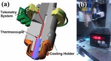
Uncoated DP780 sheets of 1.5 mm in thickness, 100 mm in length and 30 mm in width with a chemical composition of 0.15C-1.8Mn-0.35Si-0.6Cr-Fe (wt%) were used in FSSW. The carbon equivalent (CE) of DP780 was calculated as ~0.57 (wt%) by means of the following equation: CE = C + Mn/6 + (Ni + Cu)/15 + (Cr + Mo + V)/5. FSSW was conducted at the rotation rates of 500, 1000 and 1500 r/min with a constant welding time of 4 s and a fixed welding load of 20 kN. A W-25Re (wt%) tool consisting of a concave shoulder of 10 mm diameter and a pin of 4 mm diameter and 1.8 mm length, and a liquid cooling holder (MegaStir Technologies, USA) maintaining a temperature of ~20 ° C were adopted in FSSW as shown in Fig. 1. A telemetry measurement system (MegaStir Technologies, USA) placed on the cooling holder was used to measure the peak temperatures at a location 1 mm from the shoulder via a K-type thermocouple (Fig. 1). The equilibrium temperatures for the DP780 steel at the A1 and A3 points were calculated by Thermo-Calc software. The FSSW samples were sectioned across the center of the keyhole, polished and then etched with a solution of 95 mL ethanol and 5 mL nitric acid. Microstructures were characterized by optical microscopy (OM) and scanning electron microscopy (SEM), and the phase fractions were analyzed by Scion software. Element distributions were measured by JEOL5853-type electron probe microscopic analyses (EPMA). Electron backscatter diffraction (EBSD) orientation maps were obtained by using the ZEISS SUPRA 55. The Vickers hardness values were measured by Future-Tech machine with a load of 200 g for 10 s. Three tensile shear samples produced by FSSW at each rotation rate were used to evaluate the average shear failure loads using Instron testing machine at a constant strain rate of 1 × 10⁻³ s-1.
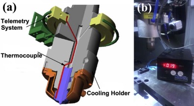 | Fig. 1. Telemetry measurement system and liquid cooling holder. |
3. Results and Discussion
3.1. Influence of rotation rates on microstructure
Fig. 2shows the cross-sectional macrographs of the FSSW DP780 joints made at various rotation rates, i.e. various heat input conditions. No defect was detected in these FSSW joints. This means that the sound joints could be achieved under a wide heat input range of 500 to 1500 r/min, showing sufficient plastic flow during the FSSW DP780 process. All the welds exhibit a typical basin-shaped outline with a keyhole. As reported previously in the FSSW DP steel joints[10 , 11], the FSSW DP780 joint was classified as three zones, the SZ, heat affected zone (HAZ) consisting of inner HAZ (IHAZ) and outer HAZ (OHAZ), and parent material (PM), as shown in Fig. 2(a). Furthermore, it is indicated that increasing the rotation rate creates the increase in the bonding interface width “ a” and the reduction in the thickness “ b” of the upper sheet. This is because with increasing rotation rate, the enhanced heat input facilitated both the plastic flow and heating diffusion between the upper and lower sheets, and reduced the deformation resistance of the upper sheet. However, both the bonding interface width and the thickness of the upper sheet would exert a significant effect on mechanical properties of the FSSW joints.
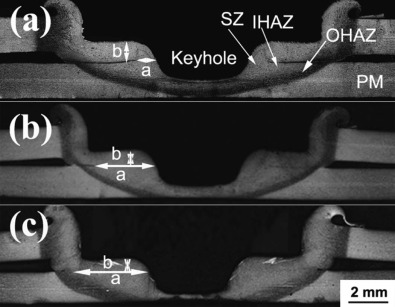 | Fig. 2. Cross-section macrographs of FSSW DP780 at rotation rate of: (a) 500 r/min, (b) 1000 r/min, (c) 1500 r/min. |
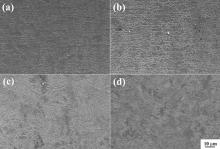
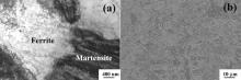
Microstructural characteristics of the PM, HAZ and SZ of the FSSW DP780 joints at the rotation rate of 1000 r/min are shown in Fig. 3. The PM is characterized by bulky ferrite and fine martensite mainly distributed near ferrite boundaries (Fig. 3(a)). The OHAZ and the IHAZ exhibit the dual phase of ferrite and martensite, and the single martensite phase, respectively. In fact, various microstructural characteristics in the two sub-regions of the HAZ were related to the different peak temperatures experienced during the FSSW thermal cycle. The peak temperature of the OHAZ fell in the dual phase field of α and γ , thereby resulting in the partial austenitization of ferrite in the PM on heating during FSSW. Therefore, the dual phase of ferrite and martensite was achieved on cooling after FSSW due to the higher hardenability of DP780 with a CE of 0.57 (wt%). For comparison, in the IHAZ where a peak temperature above A3 occurred, the original dual phase structure was fully-austenitized, and then was transformed into full martensite phase on cooling after FSSW.
To explore the microstructural evolution of the SZs at various rotation rates, it is quite necessary to obtain the peak temperature during FSSW. The telemetry measurement system presented in Fig. 1(b) reveals that at the rotation rates of 500, 1000 and 1500 r/min, the peak temperatures adjacent to the shoulder are 868, 945 and 1040 ° C, respectively. However, according to the temperature distribution during FSSW, the peak temperatures within SZs should exceed those measured near the shoulder. Through the Thermal-Calc software, the temperatures of A1 and A3 for the DP780 steel used in FSSW were determined to be 682 and 815 ° C, respectively. Clearly, the peak temperatures in the SZs at various rotation rates surpassed A3 temperature. Fig. 3(d) shows that the SZ at 1000 r/min is composed of finer martensite phase than that in the IHAZ. At the rotation rate of 1000 r/min the FSSW causes a high peak temperature above A3 and a severe plastic deformation, thereby resulting in the appearance of the full austenitization and dynamic recrystallization (DRX) in the SZ. Therefore, the fine and equiaxed austenitic grains were produced on heating during FSSW, and then were transformed into fine martensite on cooling after FSSW. Similarly, the full martensite was also detected in the SZs of the FSSW DP600 and DP980 steels at the rotation rate of 3000 r/min [10 , 11]. However, the bainite was found in the SZ of the FSSW DP600 steel at the rotation rate of 1500 r/min[12], which was mainly attributed to the lower hardenability of the DP600 with a CE of 0.24. Microstructural characteristics of the SZs at the rotation rates of 500 and 1500 r/min are presented in Fig. 4. Similar to that in the SZ at 1000 r/min, the full martensite was observed in the SZ at the rotation rate of 1500 r/min because of the occurrence of the high peak temperature above A3. However, in addition to martensite, a certain amount of fine second phase with an average size of ~3 µ m were detected in the SZ at the lowest rotation rate of 500 r/min. Furthermore, a remarkable thermo-mechanical affected zone (TMAZ) was found near the SZ at 500 r/min. This was due to the poor plastic flow at the lower heat input.
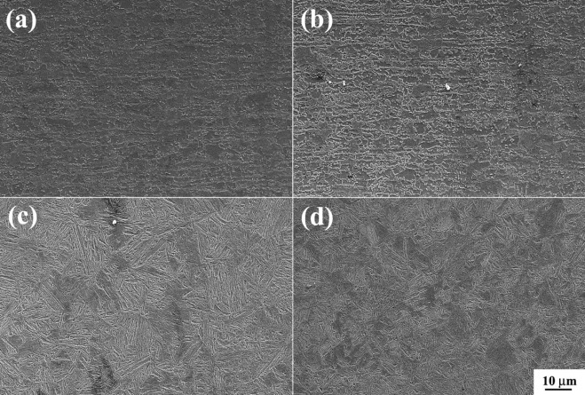 | Fig. 3. Microstructural characteristics of: (a) PM, (b) OHAZ, (c) IHAZ and (d) SZ at rotation rate of 1000 r/min. |
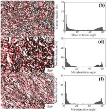
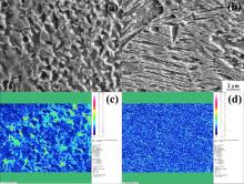
Fig. 5 shows the EBSD maps in the SZs at 500, 1000 and 1500 r/min, in which the black and red lines represent the high angle grain boundaries (HAGBs, grain boundary misorientation angle ≥ 15° ) and low angle grain boundaries (LAGBs, 2° < grain boundary misorientation < 15° ), respectively. The fractions of the HAGBs in the SZs at 500, 1000 and 1500 r/min are identified to be 53.7%, 44.1% and 42.4%, respectively. It is evident that the higher fraction of HAGBs in the SZ at 500 r/min is accounted for the absence of sub-grain boundaries within the second phase. The distribution maps of carbon element in the SZs at 500 and 1500 r/min are revealed in Fig. 6by means of EPMA. For the higher rotation rate of 1500 r/min, the homogeneous carbon element is distributed throughout the SZ, which is associated with the single martensite phase shown in Fig. 4(a). Nevertheless, for the lower rotation rate of 500 r/min, the distribution of carbon element in the SZ is highly heterogeneous, and the higher and lower carbon regions correspond roughly to the supersaturated martensite and the second phase, respectively. The second phase was further examined by TEM as shown in Fig. 7(a). The TEM image reveals that martensite and second phase correspond well to lath martensite and polygonal ferrite, respectively. Based on above analyses, the fine second phase is identified as the polygonal ferrite containing less carbon content and sub-structures.
Considering previous investigations on the transformed products during the FSW/FSSW steels[10, 11, 12, 13, 14, 15, 16, 17, 18, 19 , 20] the fine ferrite in the SZ at 500 r/min might be formed during the partial austenitization during FSSW or continuous cooling after FSSW. On the one hand, based on the IHAZ at 500 r/min consisting of full martensite (Fig. 7(b)) and previous temperature measurement, the peak temperature in the SZ at 500 r/min is identified to exceed A3. Therefore, the original dual phase structure was fully-austenitized during FSSW, and the fine ferrite in the SZ did not come from the austenitizing duration. On the other hand, the cooling rates in the SZs at higher heat inputs of 1000 and 1500 r/min were faster than the critical cooling rate of forming full martensite, because of the occurrence of full martensite shown in Fig. 3 and Fig. 4). It was noted that the lower heat input can create the faster cooling rate after welding[21]. Obviously, the cooling rate in the SZ at the lowest heat input of 500 r/min also exceeded the critical cooling rate of forming full martensite. Therefore, the pro-eutectoid ferrite was not produced during continuous cooling after FSSW. Additionally, the fractions of ferrite in the SZ and TMAZ were identified to be 21% and 6%, respectively, by using scion software (Fig. 4(b)). However, under the single heat cycle during FSSW, the fraction of ferrite in the SZ would be lower than that in the TMAZ, because the higher peak temperature in the SZ created the austenitization of more ferrite in the PM. On the basis of the above analyses, it is evident that for the FSSW process, apart from the thermal cycle, the severe plastic deformation might produce significant influence on forming the second phase.
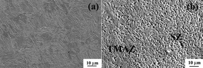 | Fig. 4. Microstructures of SZs at: (a) 1500 r/min, (b) 500 r/min. |
It is well known that the severe plastic deformation at temperatures just higher than A3 can cause enhancement of the transformed temperature of austenite to ferrite. This is attributed to the sharply increased nucleation sites at both austenitic matrix and boundaries, thereby leading to the appearance of deformation induced ferrite transformation (DIFT) [22, 23 , 24]. However, the DIFT disappeared when the deformed temperature was significantly higher than A3, because the significantly coarsened austenitic grains reduced rapidly the nucleation sites of the ferrite. Recently, Yada et al.[22] and Hodgson et al.[23] reported that steel strips consisting of ferrite with an average size of ~1 µ m were fabricated through the hot rolling at a temperature slightly higher than A3 by means of the action of the DIFT. Furthermore, it was documented that the excessively higher strain and strain rate during FSW could reach 80 and 160 s-1, respectively[25]. Thus, the DIFT was able to occur within the SZ of FSSW DP780 at 500 r/min, where a peak temperature is above 868 ° C exceeding A3 (815 ° C). However, the effect of the peak temperatures and degree of the plastic deformation during FSSW on the DIFT is relatively complicated. It was needed to investigate further the DIFT during FSSW of steels.
Generally, to obtain the fine dual phase structure with sound mechanical properties in the welds, the lower heat inputs corresponding to the peak temperatures between A1 and A3 were required in the FSW low alloy steels. For example, Fujii et al.[26] reported that a FSW S35C steel was conducted in the two-phase region of α and γ by using 400 r/min and 200 mm/min, and a dual phase structure of ferrite and pearlite was produced with higher strength. Furthermore, a dual phase structure of ferrite and martensite was achieved in the friction stir processed (FSP) plain steel by Xue et al. at 400 r/min and 50 mm/min under water cooling[27]. However, the lower peak temperatures during the FSW steels caused easily poor plastic flow and greatly deformed force of the welding tools [28 , 29]. In the present work, at the rotation rate of 500 r/min associated to higher peak temperature above A3, the dual phase structure of ferrite and martensite was produced through the action of DIFT. Obviously, the higher peak temperature could not only produce the dual phase structure, but also decrease the welding defects and prolong the useful life of the welding tool due to the sufficient plastic flow. Therefore, achieving the sound joints at rather high heat inputs had practical importance to better optimize the welding parameters.
 | Fig. 5. Grain boundaries distributions of SZ at rotation rate of: (a, b) 500 r/min, (c, d) 1000 r/min, (e, f) 1500 r/min. |
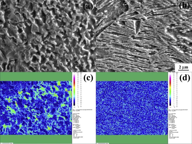 | Fig. 6. Distribution maps of carbon element of SZ at rotation rate of: (a, c) 500 r/min, (b, d) 1500 r/min. |
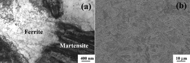 | Fig. 7. Microstructures of: (a) SZ (TEM image), (b) IHAZ (OM image) at 500 r/min. |
3.2. Influence of rotation rates on mechanical properties
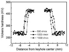
Fig. 8shows the Vickers hardness profiles of the FSSW DP780 joints along the centerline of the lower sheets at various rotation rates. Similar to studies on FSSW DP590 by Ohashi et al.[15], the SZ at 1000 and 1500 r/min exhibited the maximum hardness values because of the occurrence of the full martensite phase (Fig. 3 and Fig. 4)). Although at the rotation rate of 500 r/min some ferrite occurred in the SZ, the SZ exhibited the maximum hardness values due to the strengthening of the fine dual phase structure (Fig. 4(b)). The HAZs at various rotation rates had higher hardness values than the PM, because more ferrites in the PM were transformed into martensite during FSSW. Additionally, the minimum hardness values fell between the OHAZ and PM, which should be attributed to the somewhat annealing softening.
 | Fig. 8. Hardness profiles of FSW DP780 joints at various rotation rates. |
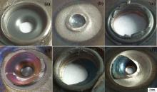
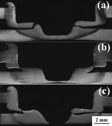
At the rotation rates of 500, 1000 and 1500 r/min, the average shear failure loads of the FSSW DP780 joints reached 10.7, 18.2 and 12 kN, respectively, which exceeded 10.3 kN for RSW 1.5 mm DP780 specified by AWS[30]. This indicates that the mechanical properties of the FSSW DP780 are comparable and even superior to that of RSW DP780. Previous studies on FSSW DP780 identified that the failure load increased as increasing the extent of the bonding interface, which consisted of both the SZ and the interface diffusion zone[13]. However, in the present work, the maximum failure load was obtained in the weld at the rotation rate of 1000 r/min, where the medium-length interface was observed (Fig. 2(b)). Fig. 9 and Fig. 10reveal the top and cross-sectional views of the shear fracture welds at various rotation rates. It is seen that for welds obtained at 500, 1000 and 1500 r/min, the crack propagates through the interface, the upper sheet, and both the upper sheet and interface, respectively. This implies that the failure loads of the welds at various rotation rates are the same as those of the fracture locations. In this case, the FSSW produces two competitive factors of the interfacial bonding and the thinning of upper sheet influencing the failure load of FSSW joints. Under the lower rotation rate of 500 r/min, although the upper sheet exhibits some thinning, the failure load of the upper sheet is higher than that of the interface due to the insufficient heating diffusion at the interface. Therefore, the tensile shear sample fractures through the interface. With increasing rotation rate, the enhanced heat input causes a continuous increase in the interfacial failure load and decrease in the failure load of the upper sheet. When the interfacial failure load is slightly higher than that of the upper sheet, the maximum failure load of 18.2 kN is made in the weld at 1000 r/min with the fracture occurring at the upper sheet. At the highest rotation rate of 1500 r/min, more thin upper sheet results in further reduction in the failure load. Furthermore, Fig. 9 and Fig. 10 indicate that the specific fracture locations of the welds at both 1000 and 1500 r/min occur within the IHAZ, but do not occur at the lowest hardness zone between the PM and OHAZ. This is attributed to the fact that the significantly thinned IHAZ exhibits the lower failure load.
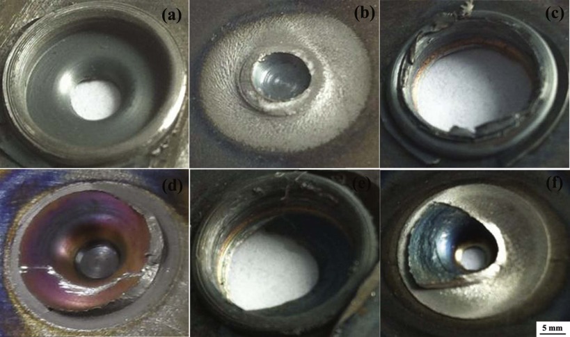 | Fig. 9. Top views of failed FSSW DP780 joints at rotation rates of: (a, b) 500 r/min, (c, d) 1000 r/min, (e, f) 1500 r/min. |
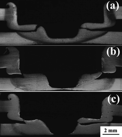 | Fig. 10. Cross-section views of failed FSSW DP780 joints at rotation rates of: (a) 500 r/min, (b) 1000 r/min, (c) 1500 r/min. |
Recently, Ohashi[11] suggested that a shear failure load of 12 kN was made in the FSSW joint of 1.2 mm thick DP980 steel at 3000 r/min. However, this weld was joined only by the SZ without obvious diffusion bonding, which was likely to be due to the low frictional heating resulting from lower welding load of 5 kN. However, Santella et al.[13] reported that at a relatively high tool load of 31.8 kN and a rotation rate of 1600 r/min, a higher failure load of 15.6 kN was yielded in the FSSW 1.5 mm thick DP780 due to the substantial diffusion bonding. In the present work, a tool load of 20 kN and a rotation rate of 1000 r/min were used in FSSW DP780, finally obtaining a maximum failure load of 18.2 kN. Therefore, under the optimum tool load and rotation rate, the sound FSSW joint with excellent mechanical properties was achieved.
4. Conclusions
(1)At a wide heat input range from 500 to 1500 r/min with a constant tool load of 20 kN, the sound FSSW DP780 joints were achieved without defects. With increasing rotation rate, the interface bonding between the upper and lower sheets became more intimate, and the upper sheet was thinned significantly.
(2)At the lowest rotation rate of 500 r/min, the DIFT appeared in the SZ, which consisted of the fine dual phase structure of ferrite and martensite. At the higher rotation rates of 1000 and 1500 r/min, the single martensite phase was found in the SZs.
(3)The maximum shear failure load as high as 18.2 kN was achieved at the rotation rate of 1000 r/min with fracture occurring in the IHAZ of the thinned upper sheet.
This work was supported by the National Natural Science Foundation of China (No. 51001023), the Fundamental Research for the Chinese Central Universities (No. N120407004) and the National High Technology Research and Development Program of China (No. 2015AA03A501). The authors are particularly grateful to Prof. R.D. Liu, the Ansteel Group Co., China, for providing the experimental materials.
The authors have declared that no competing interests exist.
Reference
| [1] |
|
| [2] |
|
| [3] |
|
| [4] |
|
| [5] |
|
| [6] |
|
| [7] |
|
| [8] |
|
| [9] |
|
| [10] |
|
| [11] |
|
| [12] |
|
| [13] |
|
| [14] |
|
| [15] |
|
| [16] |
|
| [17] |
|
| [18] |
|
| [19] |
|
| [20] |
|
| [21] |
|
| [22] |
|
| [23] |
|
| [24] |
|
| [25] |
|
| [26] |
|
| [27] |
|
| [28] |
|
| [29] |
|
| [30] |
|