


Microstructure and Mechanical Properties of Al2O3/ZrO2 Directionally Solidified Eutectic Ceramic Prepared by Laser 3D Printing
Cite this Article
Zhi Liu, Kan Song, Bo Gao, Tian Tian, Haiou Yang, Xin Lin, Weidong Huang. Microstructure and Mechanical Properties of Al2O3/ZrO2 Directionally Solidified Eutectic Ceramic Prepared by Laser 3D Printing . Journal of Materials Science & Technology, 2016, 32(4): 320-325 
Permissions
Copyright reserved, Editorial board of Journal of Materials Science & Technology
Microstructure and Mechanical Properties of Al2O3/ZrO2 Directionally Solidified Eutectic Ceramic Prepared by Laser 3D Printing
Abstract
Directionally solidified eutectic ceramics such as Al2O3/ZrO2 are promising structural materials for applications in harsh environment with an ultrahigh temperature. In this work, through adopting assistant heating laser 3D printing, Al2O3/ZrO2 eutectic samples were manufactured with suppressing the formation of cracks. The dependence of the average rod spacing ( λav) on the scanning rate ( V) follows a relation with λav V0.5 = 1 µm1.5 s-0.5. Typical eutectic microstructures, so-called complex regular, were analyzed with respect to its evolution with modulating the growth conditions. Formation mechanism of the solidification defect, shrinkage porosity, was discussed and the defect is found to be significantly suppressed by optimizing the solidification parameters. The maximum hardness and fracture toughness are measured to be 16.7 GPa and 4.5 MPa m1/2, respectively. The interplay between the propagation of cracks and the Al2O3/ZrO2 interface is discussed.
Keyword:
Al2O3; ZrO2; Eutectic; Solidification
1. Introduction
Alumina based directionally solidified eutectic ceramic (DSEC), owing to its excellent high temperature mechanical properties, is recently considered to be a promising alternative to nickel based superalloy, for the fabrication of a new generation aero space engine turbine blade[1], [2], [3 , 4]. For instance, the flexure strength of Al2O3/ZrO2(Y2O3) eutectic is about 800 MPa at 1673 K[5] and the value of Al2O3/Y3Al5O12(YAG)/ZrO2 reaches up to 860 MPa at 1873 K, which is nearly 2 times larger than that of the a-axis sapphire (approximately 450 MPa)[6]. Additionally, Chen et al.[7] studied the effect of cooling rate on the microstructure and mechanical properties of Al2O3/YAG/ZrO2 eutectic ceramic and the obtained fracture toughness was 4.13 ± 0.8 MPa m1/2. Fu et al.[8] prepared the Al2O3/YAG/ZrO2 eutectic with a refiner microstructure by the use of melt superheating. Unlike conventional ceramic, the sintering and the post heat-treatment are not needed in the preparation of DSEC. However, due to their high melting point (> 2073 K), costly crucible has to be used in the directionally solidification apparatus during fabrication. Additionally, the adoption of traditional cold-working manufacturing of these materials for fabrication of a pre-designed device component is very difficult due to the intrinsic brittleness of the oxides. These disadvantages greatly impede the industrial application of DSEC.
Recently, laser three dimensional (3D) printing has been demonstrated with several intriguing characteristics, e.g. mold free, highly flexible, and low cost, and is proven to be a promising technique in aviation industry and medical science where sophisticated components are desired[9 , 10]. Developing the method for a precise and rapid fabrication of DSEC parts by the laser 3D printing is highly desired for the development and application of the advanced ceramics. For instance, Yves-Christian et al.[11] produced the net shaped samples with nano-sized microstructures and flexural strengths of above 500 MPa. Additionally, Mitteramskogler et al.[12] prepared several ceramic parts by using the laser 3D printing, and the relevant critical technologies were discussed. However, during the direct application of the 3D printing to the ceramics, a large solid temperature gradient, due to the local heat input by the focused laser beam, will be a critical problem as micro-cracks may occur in the samples due to the high local stresses. In principle, one straightforward method for diminishing and suppressing the formation of the cracks is preheating the sample to reduce the temperature gradient. For instance, Yves-Christian et al.[11] preheated the sample by a CO2 laser, and the preheating area is about 30 mm × 40 mm and the net-shaped samples of almost 100% densities were obtained.
In this work, a preheating assisted laser 3D printing is designed for processing DSEC focusing on the precise fabrication technology, solidification behavior and the mechanical properties of DSEC. Moreover, taking account of the high stress induced by laser processing, the target material was carefully chosen. Among the several well-investigated DESC systems, Al2O3/ZrO2 eutectic possesses the highest fracture toughness at room temperature (7.8 MPa m1/2)[13] compared with Al2O3/Y3Al5O12 (2-2.4 MPa m1/2)[14], Al2O3/Er3Al5O12 (1.9 MPa m1/2)[15], Al2O3/GdAlO3 (5-6 MPa m1/2)[1] and Al2O3/Y3Al5O12/ZrO2 (4.3 MPa m1/2)[16] eutectic. Therefore, Al2O3/ZrO2 eutectic is selected as the target material, which tends to bear the high stress during cyclic heating and cooling under the laser 3D printing. Furthermore, the microstructure evolution of Al2O3/ZrO2 eutectic is investigated by examining the behavior of the complex regular eutectic microstructure. Additionally, the formation mechanism of the typical solidification defects is analyzed by considering the solidification sequence, and the solidification defects are found to be eliminated by optimizing the processing parameters. Finally, the relationship between the mechanical properties of Al2O3/ZrO2 eutectic and the processing parameters is established. Finally, the toughening mechanism of ZrO2 is discussed with consideration of the cracks propagation pattern.
2. Experimental
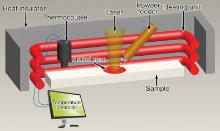
The setting of the equipment and the schematics of experimental process of the laser 3D printing are shown in Fig. 1, which consists of a PRC2000 continuous wave CO2 laser, a four-axis numerical control working table, a powder feeder with a lateral nozzle and a preheating system close-loop controlled by the thermal couple and the temperature controller (Shimaden, SRS13A). The whole experimental process was carried out in a controlled atmosphere glove box. The laser was mounted on an overhead carriage, and the beam was directed into the glove box through a window on top of the chamber. The controlled atmosphere glove box was filled with argon gas, and argon gas was also used to deliver the oxide powders.
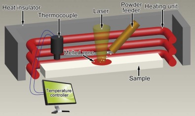 | Fig. 1. Schematic diagram of the equipment and the experimental process of the laser 3D printing. |
Commercial powders of 58.5 wt% Al2O3 and 41.5 wt% ZrO2 compositions were used to prepare precursors. The ZrO2 component includes 8 wt% Y2O3 for stabilization of the tetragonal phase of ZrO2 at room temperature. The oxide powders were mechanically mixed by wet ball milling with an aqueous solution of polyvinyl alcohol to obtain a homogeneous slurry and then dried at 473 K in air for 1 h. Afterward, the 70 mm × 10 mm × 5 mm bar precursors were prepared by uniaxial die pressing at 25 MPa for 10 min, followed by pressureless sintering at 1673 K for 2 h to increase the density and provide handing strength. The powder of Al2O3/ZrO2 eutectic with the size of ~150 µ m and spherical shape produced by pelleting was laser deposited on the ceramic precursor.
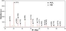
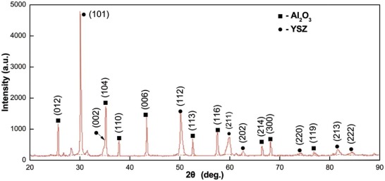 | Fig. 2. XRD pattern of the Al2O3/ZrO2 DSEC prepared by the laser 3D printing. |
The substrate was preheated to 1000 ° C. The laser beam was directed to the substrate to create a molten pool into which the eutectic powders were injected through the powder feed nozzle. The oxide powders were melted and subsequently resolidified to form the clad layer. The laser 3D printing parameters are listed in Table 1. The crack free samples with the size of 20 mm × 8 mm × 8 mm can be obtained.
| Table 1 Processing parameters of laser 3D printing |
The solidified samples were treated by general metallographic analysis methods. The microstructure of the composite were determined by scanning electron microscopy (SEM, JSM-5800), energy dispersive spectroscopy (EDS, Link-Isis), and X-ray diffraction (XRD, Rigakumsg-158).
The rod spacing was evaluated by scanning the transverse sectional images along a chosen line being perpendicular to most of the phase domains traversed, and then calculating the number of identical pixels in successive segments along the line[17, 18, 19 , 20]. The average rod spacing (λ av) is obtained by the arithmetic average of all of the measured values.
The hardness and fracture toughness are measured on the polished surface of the samples at room temperature by using the Vickers indentation technique following the ASTM C1327-99 standard. The indentations were made using 9.8 N loads for 15 s, and at least ten valid microindentations were conducted in each cross-section. The hardness and fracture toughness are calculated according to the following equations proposed by Niihara[21] for Palmqvist cracks:
Hv=0.4636P/a2 (1)
KIC=0.035(E/Hv)2/5 (a/l)1/2Hva1/2Φ 3/5 (2)
where Hv is the Vickers hardness, KIC is the fracture toughness, E is the Young's modulus of the material (we have taken the value of 343 ± 7 GPa measured by Pastor et al. [13]), P is the indentation load, a is half of the indentation diagonal, l is the crack length and Φ ≈ 3 is a constrain factor. This method is simple, convenient, nondestructive and low-cost to evaluate the hardness and fracture toughness of small and relatively brittle specimens. The sample size is large enough for the Vickers indentation test. Such technique has received great attention in recent years for measuring the mechanical properties of ceramic [22, 23, 24, 25].
3. Results and Discussion
3.1. Microstructure evolution
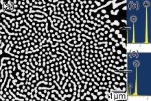
The XRD analysis indicates that the microstructure is composed of Al2O3 and ZrO2 phases (Fig. 2). Fig. 3 shows the typical transverse section microstructure (Fig. 3(a)) and EDS analysis of the phases with different colors (Fig. 3(b, c). It indicates that the black zone is Al2O3 phase (Fig. 3(b)) and the white zone is the ZrO2 phase (Fig. 3(c)).
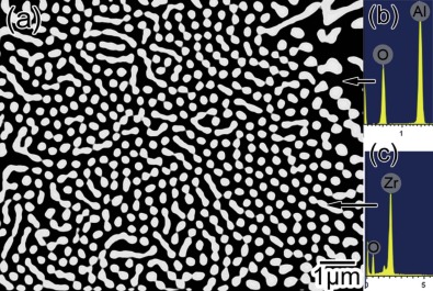 | Fig. 3. (a) Microstructure of transverse cross-section section; (b) and (c) EDS spectra of Al2O3 and ZrO2, respectively. |
The microstructure of Al2O3/ZrO2 eutectic taken from the longitudinal section (Fig. 4(a)) and the transverse section (Fig. 4(b)) shows a typical columnar colony characteristic. The colonies form as a result of the presence of constitutional undercooling associated with the growth restrictions and the faceting phase. The formation of the colonies promotes the structural stability because constitutional undercooling is relieved, similar to the signal-phase alloy. In addition, it can be found that the colonies are surrounded by coarse granular microstructure. The inter-colony spacing decreases when the scanning rate increases and is suggested to be approximately equal to D/V[26], where D is the diffusion coefficient and V is the scanning rate. The measured results are shown in Fig. 5. Furthermore, the characteristic eutectic interspacing under different scanning rates is also shown in Fig. 5. The average rod spacing measured inside the colonies shows an inverse square-root dependence on scanning rate according to λ avV0.5 = 1 µ m1.5 s-0.5, just as the prediction of JH model[27]. This result is accordance with that reported by Lee et al.[18].
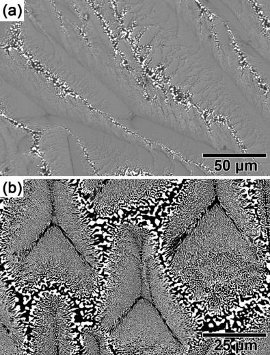 | Fig. 4. Typical microstructure of the Al2O3/ZrO2 DSEC taken from the longitudinal cross-section (a) and the transverse cross-section (b). |
 | Fig. 5. Measured eutectic rod spacing and inter-colony spacing of Al2O3/ZrO2 DSEC samples as a function of scanning rate. |
The characteristic microstructure of the Al2O3/ZrO2 eutectic colonies exhibits a complex regular morphology. A similar phenomenon had been observed in cyclohexane/camphene[28], Pb/Bi[28] and Al/Ge[29] eutectic systems. The complex regular microstructure consists of an array of ZrO2 rods which are regular over small areas, around a well-defined Al2O3 spine. This structural characterization arises from the growth of a macrofaceted projection at the solid/liquid interface, which is schematically shown in Fig. 6(a). The eutectic structure is regular on each macrofacet. Fig. 6(b-d) are the close-up view of the area defined by the circle in Fig. 6(a) and represent the microstructure evolution on the apex of the colonies. A sharp contact angle is formed at the apex of the solid/liquid interface. The growth direction of the rod eutectic is perpendicular to the solid/liquid interface (Fig. 6(b)). During the eutectic growing process, the rod spacing below the β 1 rod maintains constantly and steadily. However, the α single phase constantly coarsens at the apex of the colony above the β 1 rod, which is unstable under the eutectic composition. When the scale of the α single phase exceeds a certain value, the nucleation of the β phase will form at the apex of the α phase due to the solute enrichment (shown by the arrows in Fig. 6(c)). Therefore, the local rod spacing reasonably decreases and the system tends to be stable (Fig. 6(d)). Furthermore, the formation of the regular structure can be attributed to that each rod within the regular region possesses the same crystal facet. The reported orientation relationship of Al2O3/ZrO2 eutectic is [0001] alumina‖ < 011 > zirconia parallel to the growth direction[30]. In a word, the forming mechanism of the complex regular microstructure is associated with a growth normal to the macrofaceted solid/liquid interface accompanied by the nucleation of ZrO2 on the coarsening edge at the apex of the colony.
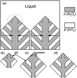 | Fig. 6. (a) Schematic diagram of solid/liquid interface of the eutectic colonies; (b)-(d) the microstructure evolution on the apex of the eutectic colonies. |
3.2. Solidification defect
Fig. 7 shows typical shrinkage porosity in the inter-colony area under the scanning velocity of 200 µ m/s. The solidification defects often occur in the final solidified area. The occurrence of these defects is attributed to the volume contraction in the cooling stage. There are three quite different types of contractions when cooling from the liquid state to room temperature: the liquid contraction, the solidification contraction and the solid contraction[31]. The shrinkage porosities form at the last stage[32 , 33]. As discussed above, the solid/liquid interface of Al2O3/ZrO2 eutectic is not planar (like Al2O3/Y3Al5O12 eutectic[20]) but macrofaceted. This means that the solid contraction is not integral parallel to the solidification direction but independent in every colony like the dendritic solidification. The contraction direction is schematically shown by the arrows in Fig. 6(a). If the induced holes cannot be adequately fed by the liquid, the shrinkage porosities occur. It should be noted that the shrinkage porosities are not found in the samples prepared by the directional solidification methods, such as micro-pulling down[18] and laser floating zone[13]. The reason is that the growth direction of the eutectic colonies is vertical and parallel to the direction of heat flow. However, the growth direction of the eutectic colonies is acclivitous to the gravity in laser 3D printing. Therefore, the induced pressure of the liquid in laser 3D printing is smaller than that in directional solidification.
 | Fig. 7. Typical shrinkage porosity in the Al2O3/ZrO2 DSEC under the scanning rate of 200 µ m/s. |
The basic idea to restrain the formation of the shrinkage porosity is the enhancement of the feeding ability of the liquid. Appropriate approaches include an increase of the laser power and a decrease of the scanning rate. This can increase the liquid temperature and the feeding time to improve the fluidity and the feeding ability. The experimental results exhibit that the shrinkage porosity is not found in the samples prepared under the scanning rate smaller than 100 µ m/s and the laser power larger than 400 W.
3.3. Hardness and fracture toughness
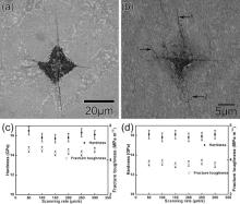
The morphology of a typical indentation crack on the polished surface is shown in Fig. 8(a, b). The hardness and the fracture toughness measured on the transverse section and the longitudinal section are plotted in Fig. 8(c, d) as a function of the scanning rate. The results exhibit that the mechanical properties maintain constant with the varied scanning rate. The average hardness obtained on the transverse section and the longitudinal section are 16.0 GPa and 16.7 GPa, respectively, consistent with the results measured from the samples prepared by laser horizontal zone melting[34]. Additionally, the fracture toughness also approaches the reported value[34]. The averaged values are 4.5 MPa m1/2 and 3.8 MPa m1/2 on the transverse section and the longitudinal section, respectively.
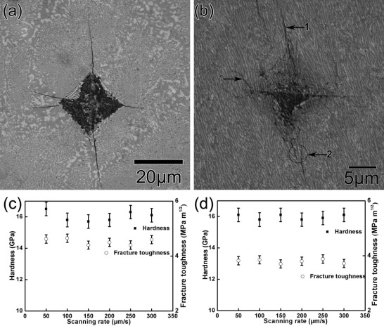 | Fig. 8. Typical indentation crack on the polished surface of the Al2O3/ZrO2 DSEC under the indentation load of 9.8 N (a) and 2 N (b); and the dependence of the hardness and fracture toughness as a function of the scanning rate measured from the transverse section (c) and the longitudinal section (d). |
We also observed two important phenomena including: (1) the fracture toughness obtained on the transverse section is higher than that on the longitudinal section; (2) the length of the crack aligned perpendicular to the extension direction of the eutectic colonies is shorter than that parallel to it (Fig. 8(a)). It can be attributed to the interaction between the cracks and the Al2O3/ZrO2 interface.
The thermal expansion coefficients of Al2O3 (8.4 K-1 10-6) is remarkably different from the ZrO2 phase (12.65 K-1 10-6). ZrO2 is subjected to tensile residual stresses and the Al2O3 phase is often subjected to compressive residual stresses in the Al2O3/ZrO2 eutectic system[3 , 35]. According to Frazer[35], residual stresses measured in the Al2O3 phase of the Al2O3/ZrO2 system are on the order of -250 to -400 MPa at room temperature. Therefore, the cracks are significantly influenced by the residual stresses when crossing the Al2O3/ZrO2 interface.
For illustrating the interaction between the propagating cracks and the phase interface, the weak cracks were prepared by adopting a moderate load in the Vickers indentation experiment. Fig. 8(b) shows the typical indentation crack under the load of 2 N. It can be observed that the cracks hardly propagate perpendicular to the phase interface. The interaction between the propagating cracks and the phase interface can be concluded as the following aspects. (1) Crack deflection. As can be seen from the tip of the indentation in Fig. 8(b), the cracks perpendicular to the phase interface immediately deflect and evolve toward the parallel direction with the phase interface. This phenomenon is similar with that reported on Al2O3/YAG/ZrO2 eutectics produced by the laser floating zone method[2]. Additionally, the crack deflection also occurs when it is propagating as shown by the arrows “ 1” . The crack deflection is an important toughening mechanism in DSEC system such as CaF2/MgO[36] and CoO/YSZ[37]. According to LLorca and Orera[3], the crack deflection is attributed to the presence of fluctuating residual stress fields and the elastic mismatch between the eutectic phases. Furthermore, Faber and Evans[38] suggested that only the crack deflection around the second phase can lead to a toughness increment of 12%-15%. (2) Crack bridging. As shown by the arrows “ 2” in Fig. 8(b), an initial crack is arrested followed by the generation of another parallel crack by the side of the initial crack tip. Such crack bridging can reduce the driving force of crack propagation due to the development of elastic bridges behind the main crack tip. It has been well established that the crack bridging in the crack wake is an effective toughening mechanisms in brittle solids and often responsible for the high toughness[3 , 39].
In a short summary, the fracture toughness is an important quantity to reflect the ability of impeding the crack propagation. Additionally, the crack propagation can be significantly affected by the presence of the Al2O3/ZrO2 interface. Denser phase interface can be identified in the cross section and the perpendicular direction of the eutectic colonies extension. Therefore, the cracks length examined on the different directions should be evidently affected by the distribution character of the phase interface.
4. Conclusions
(1)The dependence of the average lamellar spacing with the solidification rate follows the relation λ avV0.5 = 1 µ m1.5 s-0.5.
(2)The eutectic microstructure exhibits complex regular characteristics.
(3)Formation of the typical solidification defect, shrinkage porosity, can be significantly suppressed by adopting a scanning rate smaller than 100 µ m s-1 and a laser power larger than 400 W.
(4)The average hardness and fracture toughness are 16.7 GPa and 4.5 MPa m1/2, respectively.
(5)The fracture toughness obtained on the transverse section is higher than that on the longitudinal section; the length of the crack perpendicular to the extension direction of the eutectic colonies is shorter than that parallel to it.
The authors would like to thank the National Natural Science Foundation of China (No. 81170983) and China Postdoctoral Science Foundation (No. 2015M572597).
The authors have declared that no competing interests exist.
Reference
| [1] |
|
| [2] |
|
| [3] |
|
| [4] |
|
| [5] |
|
| [6] |
|
| [7] |
|
| [8] |
|
| [9] |
|
| [10] |
|
| [11] |
|
| [12] |
|
| [13] |
|
| [14] |
|
| [15] |
|
| [16] |
|
| [17] |
|
| [18] |
|
| [19] |
|
| [20] |
|
| [21] |
|
| [22] |
|
| [23] |
|
| [24] |
|
| [25] |
|
| [26] |
|
| [27] |
|
| [28] |
|
| [29] |
|
| [30] |
|
| [31] |
|
| [32] |
|
| [33] |
|
| [34] |
|
| [35] |
|
| [36] |
|
| [37] |
|
| [38] |
|
| [39] |
|