Microstructure and Corrosion Resistance of Dissimilar Weld-Joints between Duplex Stainless Steel 2205 and Austenitic Stainless Steel 316L
[Aboulfazl Moteshakker, Iman Danaee ]
]
]
|
|


The microstructure and corrosion resistance of dissimilar weld-joints between stainless steel SAF 2205 and stainless steel AISI 316L were investigated. Welding was accomplished by different types of welding wires AWS ER 347, AWS ER 316L and AWS ER 309L. To verify soundness of welded samples, nondestructive tests were performed. Metallographic samples were prepared from cross-section areas of weld-joints to investigate microstructure of different regions of weld-joints by optical microscopy and scanning electron microscopy. Corrosion resistance of weld-joints was evaluated in NaCl solution by potentiodynamic polarization and electrochemical impedance techniques. In the weld metal AWS ER 347, the brittle sigma phase was created, resulting in the decrease of weld-joint corrosion resistance. According to the results of metallurgical investigations and corrosion tests, welding wire AWS ER 309L was suitable for welding duplex stainless steel (SAF 2205) to austenitic stainless steel (AISI 316L) by gas tungsten arc welding (GTAW) process.
Stainless steels are an important class of engineering materials that have been used widely in a variety of industries and environments, specially due to good mechanical properties and corrosion resistance. Welding is an important fabrication technique for stainless steels, and generally, the stainless steels are considered as weldable materials[1, 2, 3]. Austenitic stainless steels, due to excellent properties such as corrosion resistance, ductility, toughness, and weldability, represent the largest general groups of stainless steels, which are produced in higher tonnages than any other groups. Duplex stainless steels are compositionally formulated and thermo-mechanically processed to provide a two-phase microstructure exhibiting nearly equal proportions of ferrite and austenite[4, 5, 6]. The unique properties of duplex stainless steels are strongly dependent on their “ 50/50” ferrite-austenite balance. Duplex stainless steels are becoming increasingly popular in structural applications, requiring higher strength and corrosion resistance than austenitic stainless steels, and have been employed in the onshore and offshore oil and gas, cargo holds in chemical tankers, petrochemical industries and gas-transmission lines. Therefore, a strong trend to use duplex steels as a structural material in industry has been increased[7, 8, 9, 10].
Arc welding of duplex stainless steels can produce alterations in microstructures of weldment or heat affected zone. Throughout welding of duplex steels, the microstructure of heat affected zone is almost fully ferritic, and during cooling, a solid transformation of ferrite to austenite occurs. To promote the formation of austenite during the welding of duplex stainless steels, utilization of filler metals fortified with Ni has been a common practice in industry. For welding duplex stainless steels, it is essential to use filler metals that can create 5%-10% delta ferrite in the welded microstructure, which is required to prevent solidification cracking. Although there is no specifically defined limit to ferrite content, the ferrite content at the weld metal and heat affected zone should be in the range of 25%-75% to give optimum mechanical properties and corrosion resistance[11, 12].
Dissimilar metal welding (DMW) is frequently used to join stainless steels together or to other materials in different situations such as, gas pipeline and petrochemical industry. Reasons for these combinations may be economic, property considerations, transition or cladding. Stainless steels may be involved in joints of varying degrees of dissimilarity. It is especially important to make an appropriate selection of filler metal to produce a sound joint that will give satisfactory service performance. Generally, to use benefits of both alloys, filler metals and welding process should be chosen precisely[13, 14]. There is no slag in gas tungsten arc welding (GTAW), accompanied by a good control of welding parameters, making it practical for welding dissimilar weld joints.
In stainless steels, to maintain high resistance to localized corrosion, the alloying elements must be in solid solution and homogeneously distributed. However, the balance of alloying elements can be changed by the precipitation of various secondary phases, due to microstructural alterations that resulted from improper welding conditions[15, 16]. The most common precipitates are secondary austenite (γ 2), nitrides, M23C6 carbide and Fe-Cr-Mo intermetallic phases such as σ phase, χ phase and R phase. Their presence can cause degradation of the material particularly its corrosion properties. The severity of corrosion attack depends on the nature and amount of these undesirable phases and, hence, the chemical composition of the steel as well as the production conditions[17, 18].
In this study, two different stainless steels, SAF 2205 (duplex stainless steel) and AISI 316L (austenitic stainless steel), were welded together by gas tungsten arc welding (GTAW) process, using different types of filler metals with codes AWS ER 347 (SW1), AWS ER 316L (SW2) and AWS ER 309L (SW3). These stainless steels have been individually welded under constant welding parameters to identify the appropriate filler material. The changes occurring in the microstructures of weldments and heat-affected zones (HAZs) were studied. The performance of these weld-joints in a corrosive environment was determined.
Plates of SAF 2205 (UNS 31803) duplex stainless steel and AISI 316L (1.4432) austenitic stainless steel with 8 mm in thickness were used as base materials. AWS ER 347, AWS ER 316L and AWS ER 309L in the form of welding wires were used as filler materials. The diameter of filler wires was 2.4 mm that are slightly overalloyed, principally with respect to nickel. The chemical compositions of steel plates and filler materials are given in Table 1.
| Table 1. Chemical compositions of base metals and filler materials (wt%) |
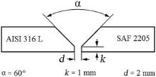
The dissimilar welded joints were made between SAF 2205 steel and AISI 316L steel by using each of the welding wires. As illustrated in Fig. 1, a V-groove edge preparation was exercised. The base metals and welding wires were cleaned with acetone, prior to welding. Base plates were fixed as the design of the fixture bars, allowing full access to the weld-joint without any interfering with the shielding gas flow. A welding power source (GTA welding machine) model “ PARS-EL 6335 licensed Merkle Germany” was employed to execute GTA welding, and a clamp meter (AC/DC) model “ Kyoritsu Kew Snap 2003A” was used to quantify current and voltage accurately during welding process. Non-consumable tungsten electrode AWS EWTh-2 with 2.4 mm diameter was utilized in a gas-cooled torch to implement GTA welding using direct current electrode negative. A 100° temperature sensitive crayon was exploited within 25 mm of the weld on the base metal to estimate interpass temperature. Weld-joints were filled with two filler passes in addition to root and cap passes as each layer was deposited in a single pass as well as all passes were scrubbed with an SS brush. Pure argon gas was used for gas shielding and back purging to impede oxidation of the welds. Welding procedure was accomplished according to AWS D1.1 and AWS C5.5/C5.5M standard, and the details of the welding parameters are listed inTable 2.
 | Fig. 1. Edge preparation for dissimilar weld-joints (V-groove joint design). |
| Table 2. Welding parameters for GTAW process of dissimilar welds of SAF 2205 to AISI 316L |
Nondestructive tests were performed to verify soundness of produced welds complied with the requirements based on AWS D1.1 standard. Visual inspections (VT) were carried out before and after welding. Prior to welding, cleanness of materials, alignment, setup and dimensions of weld-joints were checked. During welding, items such as root penetration, interpass temperature, cleanness of weld beads and conformance with the applicable procedure, i.e. voltage, amperage, heat input and travel speed, were controlled. After welding, appearance of final welds was inspected and appraised to detect typical surface discontinuities as porosity, incomplete fusion, incomplete joint penetration and cracks. To detect any weld surface discontinuities, especially cracks, liquid penetrant (PT) was executed on the weld-joints. Three spray packs were employed to PT examination, supplied from “ ELY Co.” Eventually, all weld-joints were examined via radiography test (RT), using single wall single image (SWSI) technique, to get an assurance that the welds include no internal discontinuities especially cracks and tungsten inclusions. An X-ray generator model “ Balteau 300 kV” was employed as the source of radiation. A wire-type image quality indicator (IQI), with 7 wires from number of wire 10-16 as per DIN 62, and radiographic film model “ Kodak MX 125” were used.
The microstructural features were characterized, using metallographic specimens which were cut from cross-sectional areas of the welded plates by a bandsaw machine model “ Marvel series 8-mark-i” while applying a coolant to avoid any possible change in microstructure. Twenty-five millimeters from end of each welded plate was discarded. According to ASTM E3, metallographic specimens were ground on wet SiC paper from 220, 400, 600, 800, 1000, 1200 and 2000, degreased with acetone, rinsed by distilled water and dried in dry air. Then, a sequence of polishing through 1-µ m diamond paste was performed before final polishing on 0.05 µ m alumina. All metallographic specimens were electrolytically etched using an aqueous 10% oxalic acid solution for 25-30 s at potential of 5-6 V to produce contrast among different phases. Microstructural investigations were conducted by optical microscopy (OLYMPUS DP 71) and scanning electron microscopy (SEM, Philips-XL30) operating up to 30 kV equipped with an energy dispersive spectroscopy (EDS) to analyze chemical composition of weldments and intermetallic phases, and the results were gathered by ZAF software.
The macro-section of welded-joints was evaluated to check the penetration and to measure the dilution. The ferrite content in the weldments was assessed using a computer image analysis program. It is important for the ferrite content in the HAZ and weld metals of duplex stainless steels to be crucial to obtain optimum mechanical and corrosion resistance properties.
According to ASTM G3, to evaluate corrosion performance of welded samples, electrochemical impedance spectroscopy (EIS) and potentiodynamic polarization were used in 3.5 wt% NaCl solution at 25 ± 1 ° C. All solutions were prepared using an analytical grade reagent from Merck product and doubly distilled water.
The specimens were abraded with wet SiC abrasive paper from 220, 400, 600, 800, 1000, 1200 and 2000 grit by a mechanical instrument model Struers LaboPol-1, degreased by acetone, rinsed by distilled water and dried in dry air. Afterwards, all specimens were polished by 1 µ m diamond paste before final polishing on 0.05 µ m alumina, rinsed with water and then washed by ethanol in an ultrasonic cleaner, before each electrochemical experiment.
The experiments were carried out in a conventional three-electrode cell with platinum and saturated calomel SCE electrode as the counter and the reference, respectively. The specimens were used as the working electrode with an exposed surface area of 0.196 cm2. All tests were repeated at least three times to ensure data accuracy.
All specimens were allowed to stabilize for 40 min before electrochemical tests. Potentiostat/galvanostat instrument model PGSTAT 302N Autolab (the Netherlands) was used for electrochemical tests. Potentiodynamic polarization tests were performed according to ASTM G102 and ASTM G61 at a potential scanning rate of 0.5 mV s-1, while the potential begun from -0.2 V with respect to open circuit potential (OCP) and were allowed to reach to the transpassive region to compare the localized corrosion resistance of weld metals.
Electrochemical impedance spectroscopy (EIS) was performed according to ASTM G106 at open circuit potential. The frequency of EIS tests was set in the range from 100 kHz to 10 MHz. The amplitude of the sinusoidal voltage signal was 10 mV. EIS data were evaluated and fitted by FRA software to propose equivalent circuit.
Visual assessments indicated no significant discontinuities in welded joints except a number of small undercuts, which were within acceptance criteria according to AWS D1.1. These undercuts are easily removable because of small depth, less than 0.3 mm. The results of liquid penetration exhibited no existence of surface discontinuities for weldments. Radiographs indicated that except a number of small undercuts, no cracks were distinguished throughout weld line of specimens SW1, SW2 and SW3. No bright spots were discerned within weld lines in radiographs, meaning that no tungsten inclusions were created in weld metals of all specimens, since they are brittle and decrease mechanical properties of weldments. In accordance with nondestructive investigations, it was deduced that welding parameters and welding wires were opted appropriately for this dissimilar joint from standpoint of weldability, specially non-existence of cracks.
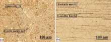
The microstructures of base metals are illustrated in Fig. 2. The microstructure of SAF 2205 comprises austenite islands in a ferrite matrix in almost equal proportions (Fig. 2 (a)), and AISI 316L has an austenitic matrix that consists of lamellar ferrite precipitates (Fig. 2 (b)). SAF 2205 and AISI 316L possess Creq/Nieq values 3.06 and 1.85 (Table 1 ), respectively, according to Welding Research Council[19].
 | Fig.2. Optical micrograph of base metals revealed by oxalic acid etching; light gray, austenite; dark gray, ferrite: (a) SAF 2205, (b) AISI 316L. |
| Table 3. Chemical compositions of weld metals (wt%) |
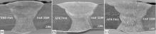
Each welded joint was filled by four welding layers and transverse sections of the welded joints, which are displayed in Fig. 3 for samples SW1, SW2 and SW3. Dilution levels were estimated using metallographic methods and image analysis program to measure the individual geometric cross-sectional areas of the deposited filler metal and melted base metal. Average dilution level for each welded joint is (35 ± 2)%. Chemical compositions of weld metals of specimens SW1, SW2 and SW3 were analyzed by a metal analyzer instrument, and the results are brought in Table 3.
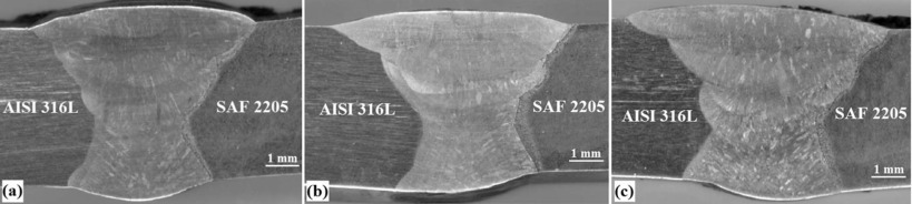 | Fig. 3. Transverse sections of the weldjoints: (a) SW1, (b) SW2, (c) SW3. |
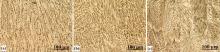
Fig. 4 shows the microstructures of the fusion zone of the weld metals SW1, SW2 and SW3 by optical microscopy. The dark gray dendrites and the light gray regions displayed in Fig. 4 (a-c) are δ -ferrite and austenite phase, respectively. At the beginning of solidification, the core of the δ -ferrite dendrites is richer in Cr, while the outer portions, which form at lower temperature, have lower Cr contents. Then upon cooling, the outer portions of the dendrites, which have less Cr, transform to austenite, and thus leave behind Cr-rich skeletons of δ -ferrite at the dendrite cores. Austenite grows epitaxially from the unmelted austenite grains at the fusion boundary, and δ -ferrite soon nucleates at the solidification front. As illustrated in Fig. 4 (c), fine equiaxed grains are created in sample SW3. One of the main reasons for fine equiaxed grains is weld pool convection, which causes fragmentation of dendrite tips in the mushy zone. These dendrite fragments are carried into the bulk weld pool and act as nuclei for new grains to form.
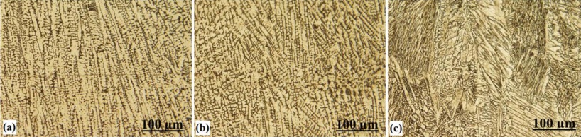 | Fig.4. Optical micrographs of weldments; light gray, austenite; dark gray, ferrite: (a) sample SW1, (b) sample SW2, (c) sample SW3. |
Ferrite contents in the weld metals were measured in three points of center line of each weld pass for all samples, with the use of image analysis program (Table 4). For all samples, upper weld passes contain lesser amounts of delta ferrite. This phenomenon is associated with slower cooling rate in upper weld passes due to the preheating of base metals resulting from prior weld passes. Table 4 reveals that ferrite content in the fusion zone of SW3 is higher than that in other samples. This is related to the highest Creq content of SW3. This phenomenon indicates the effect of chemical composition on ultimate fusion zone microstructure.
| Table 4. Mean values of ferrite content of each weld pass for all specimens (%) |
Hot cracks were not observed in the weld metal deposits for all samples. Weld metals solidified partly as ferrite shows high resistance to hot cracks formation. Therefore, from standpoint of cracking, combination of studied fillers seems to be a suitable choice for dissimilar austenite-duplex joints.
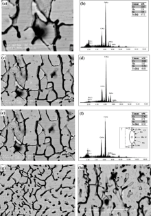
Fig. 5(a-d) depicts back scattered electron micrographs of fusion zone of SW1 and the corresponding EDS spectra. The assessment of the partitioning of major alloying elements between ferrite and austenite in SW1 by EDS analysis reveals that[20] ferrite is enriched in Cr, Mo, while austenite is enriched in Ni (Fig. 5 (b and d)). As illustrated in Fig. 5 (e), sigma phase in the weld metal of SW1 is created. The sigma phase nucleates at the ferrite-austenite interface, which grows towards the ferrite grains as a result of the eutectoid reaction (α → σ + γ )[21]. The corresponding EDS spectrum for chemical composition of sigma phase and a sketch of sigma phase nucleation at the ferrite-austenite interface are indicated in Fig. 5 (f). In the presence of large quantities of Cr and Mo, the possibility of the brittle tetragonal sigma phase (σ ) occurring in this steel rises[22, 23, 24, 25]. The existence of higher values of carbides in SW1 results in the creation of some sigma phase in ferrite-austenite interface, which grows towards the ferrite grains in the weld metal, as illustrated in Fig. 5 (e). Back scattered electron micrographs of weld metals of SW2 and SW3 show no intermetallic particles especially due to lower content of carbon (Fig. 5 (g and h)).
 | Fig. 5. Back scattered electron micrographs of fusion zones: (a) sample SW1: celtic cross shows the ferrite phase (scale is 5 μ m), (b) the corresponding EDS spectrum for chemical composition of ferrite phase, (c) sample SW1: celtic cross shows the austenite phase (scale is 10 μ m), (d) the corresponding EDS spectrum for chemical composition of austenite phase, (e) sample SW1: celtic cross shows the sigma phase (scale is 10 μ m), (f) the corresponding EDS spectrum for chemical composition of sigma phase (scale is 10 μ m), (g) sample SW2 and (h) sample SW3 (scale is 10 μ m). |
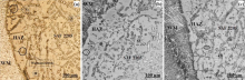
The weld metal next to the fusion line, tagged as the unmixed zone, suggests stagnant melted base metal unmixed with the filler metal. Fig. 6 (a-c) is optical micrographs of weld zones of austenitic steel side for SW1, SW2 and SW3. The unmixed zone appears as a layer, where a small fraction of the base metal has been totally melted and resolidified without undergoing any dilution.
 | Fig. 6. Optical micrographs of weld zones of austenitic steel side (WM: weld metal, UZ: unmixed zone): (a) sample SW1, (b) sample SW2, (c) sample SW3. |
As can be seen in Fig. 6 (b), both austenite and ferrite grow epitaxially at the fusion line from the base metal to the weld metal. Epitaxial growth occurs when the work-piece is a material of more than one phase[26]. During solidification, grains with their easy-growth direction < 100> essentially perpendicular to the pool boundary will grow more easily and crowd out those less favorably oriented grains[26]. This mechanism of competitive growth dominates the grain structure of the bulk weld metal as seen in Fig. 6 (a).
For all samples, there is no evidence of excessive austenite grain growth. It is probably because the austenitic microstructure consists of lamellar ferrite precipitations (Fig. 6) and also formation of ferrite along HAZ grain boundaries, which restricts grain growth. Ferrite has a lower thermal expansion coefficient than austenite[19].
Observations of the heat affected zones of all samples by metallographic microscopy indicate the ferrite grain growth occurred as depicted in Fig. 7. The driving force for grain growth is the surface energy. The total grain boundary area and the total surface energy of the system can be reduced if fewer and coarser grains are present[26].
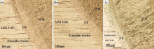
 | Fig. 7. Optical micrographs of weld zones of duplex steel side (WM: weld metal, HAZ: heat affected zone, α : ferrite phase, γ : austenite phase, γ 2 : secondary austenite phase): (a) sample SW1, (b) sample SW2, (c) sample SW3. |
During welding, the heat affected zone of duplex steel side experiences many changes including the solid state phase transformation from austenite to ferrite and vice versa. These events have important implications with respect to the final microstructure and the corresponding properties.
High ferrite content in the range of 65-72% is obtained at heat affected zones at the duplex steel side of the welds by using image analysis program. This unfavorable structure does not deteriorate the mechanical properties of the whole joints due to the very low dimensions (width: 300-400 µ m) of this zone. Examinations of the heat affected zones reveal approximate continuous networks of austenite at ferrite grain boundaries and also austenite formed as Widmanstä tten sideplates off the grain boundary, or intragranularly within the ferrite grains (Fig. 7).
Reheating the weldment allows for additional diffusion to take place, which results in further growth of austenite or nucleation of new austenite. This second nucleation is termed as secondary austenite (γ 2), which is illustrated in Fig. 7. Secondary austenite formation is most prevalent in the heat affected zone during multipass welding and can significantly alter the ferrite-austenite balance of the microstructure[19].
Optical evaluations for all samples reveal epitaxial growth (Fig. 7 (a)) adjacent to fusion boundary. However, away from the fusion line, competitive growth (Fig. 7 (c)) dominates the grain structure of the bulk weld metal.
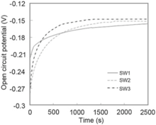
Fig. 8 shows the open circuit potential change of different welding materials. As can be seen, all specimens were stabilized in 3.5 wt% NaCl solution in 2500 s. It is reasonable to assume that the value of OCP slightly moved toward the noble potentials by increasing Cr equivalent in chemical composition of specimens. SW3 had the noblest open circuit potential, and sample SW1 had the most active (Table 5).
 | Fig. 8. Open circuit potential vs time curves for specimens immersed in 3.5 wt% NaCl solution. |
| Table 5. Quantitative measurements of open circuit potential for all specimens immersed in 3.5 wt% NaCl solution |
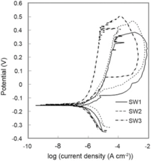
Potentiodynamic polarization plots for SW1, SW2 and SW3 in 3.5 wt% NaCl solution are presented inFig. 9. All polarization plots followed Tafel style behavior. When the potential is anodically scanned, no active current peak is evidenced, demonstrating that all specimens were previously passivated due to the air formed oxide film, probably with Cr2O3(H2O)n[27]. Fig. 9 reveals that the SW3 has the lowest current density and the noblest corrosion potential. Corrosion potential (Ecorr), corrosion current density (Icorr), pitting potential (EPit), protection (or repassivation) potential (EProt), passive current density (IP), polarization resistance (RP), and corrosion rate (CR) are listed in Table 6.
 | Fig.9. Potentiodynamic polarization curves for specimens in 3.5 wt% NaCl solution. |
| Table 6. Quantitative measurements of electrochemical parameters that resulted from Tafel extrapolation of potentiodynamic polarization curves for specimens |
The corrosion potential of sample SW1 is more negative in comparison with sample SW2, and it had a higher corrosion current density due to existence of the lower chromium equivalent (Creq). It means that chemical composition is an important parameter to analyze corrosion behavior of the samples. The corrosion resistance of Fe-Cr alloys tends to improve as the Cr content is increased. Also, the low corrosion resistance behavior of sample SW1 was attributed to the existence of some sigma phase in its weldment. Creation of sigma phase is a chromium-consumable reaction. Therefore, chromium-depleted zones surrounding sigma phase particles will be produced, which have the lowest corrosion resistance[23, 28].
An increase in the chromium equivalent via enhancing some elements specially Cr and Mo mainly improves resistance to localized corrosion. Nitrogen also has a beneficial influence on the pitting corrosion resistance[29, 30]. Since the magnitude of nitrogen in samples SW1, SW2 and SW3 was identical, it is clear that, due to the greatest value of Creq in sample SW3 relative to other samples, it has the noblest magnitudes of Epit and EProt and broader passive region. Furthermore, the value of (Epit - Eprot) for sample SW3 is lower than that for other samples. This is a sign of higher stability of the passive layer formed on sample SW3, revealing that it has the minimum tendency to pitting corrosion among all samples. In addition, sample SW2 is more resistant than sample SW1 to pitting corrosion due to the greater value of Creq, specially resulting from higher Mo in its chemical composition, resulting easily in restoring passivity[30].
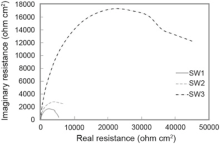
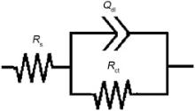
Fig. 10 presents impedance plots for SW1, SW2 and SW3 in 3.5 wt% NaCl solution at open circuit potential. The data reveal that impedance diagram consists of a depressed capacitive loop due to the charge transfer resistance and double layer capacitance. The equivalent circuit compatible with the Nyquist diagram is depicted in Fig. 11. As shown in Eq. (1), the simplest approach requires the theoretical transfer function Z (ω ) to be represented by a parallel combination of a resistance Rct and a capacitance C, both in series with another resistance Rs[31]:
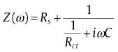
where ω is the frequency in rad/s, ω =2π fω =2π f and f is frequency in Hz. In this electrical equivalent circuit, Rs, Qdl and Rct represent solution resistance, a constant phase element corresponding to the double layer capacitance Qdl=Rn-1Cndl and the charge transfer resistance. To obtain a satisfactory impedance simulation, it is necessary to replace the capacitor (C) with a constant phase element (CPE) Q in the equivalent circuit. The most widely accepted explanation for the presence of CPE behavior and depressed semicircles on solid electrodes is microscopic roughness, causing an inhomogeneous distribution in the solution resistance as well as in the double-layer capacitance [32].
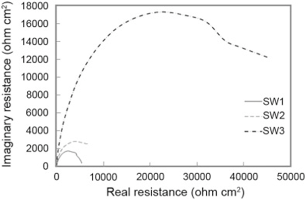 | Fig. 10. Nyquist curves for specimens in 3.5 wt% NaCl solution. |
 | Fig. 11. Equivalent electrical circuit for Nyquist curves of specimens. |
To corroborate the equivalent circuit, the experimental data are fitted to equivalent circuit, and the circuit elements are obtained. Table 7 illustrates the equivalent circuit parameters for the impedance spectra of corrosion of weldments in NaCl solution. According to the Table 7, SW3 has a greater charge transfer resistance than other sample. This indicates that the sample SW3 shows the best corrosion resistance among all samples. The increasing chromium equivalent enhances the formation of protective surface film, which has a high charge transfer resistance.
| Table 7. Quantitative measurements of electrochemical parameters that resulted from analysis of Nyquist curves for specimens |
Two different stainless steels, SAF 2205 and AISI 316L, were welded together by GTAW process, using different types of filler metals. The results of nondestructive tests confirmed no internal discontinuities especially cracks and tungsten inclusions exist in produced welds. According to microscopical observations and EDS analyses, microstructures of all samples included austenite enriched in Ni and skeletal ferrite enriched in Cr and Mo. Existence of higher values of carbon and carbides in sample SW1 relative to other samples resulted in creation of some sigma phase in ferrite-austenite interface while this phenomenon did not occur in samples SW2 and SW3. On the austenitic steel side of all samples, there was an unmixed zone as a layer, where a small fraction of the base metal was totally melted and resolidified without undergoing any dilution. On the HAZ of austenitic steel side, there was no evidence of excessive austenite grain growth due to the austenitic microstructure consisting of lamellar ferrite precipitations and also formation of ferrite along HAZ grain boundaries.
It was revealed that for all samples, upper weld passes contained lower amounts of delta ferrite. Also, the ferrite content in the fusion zone of sample SW3 was higher than that in other samples, since it had the highest Creq content. Potentiodynamic polarization data and EIS tests (Nyquist plots) confirmed that sample SW3 had higher corrosion behavior among all samples. Low corrosion resistance behavior of sample SW1 was attributed to the existence of some sigma phase in its weldment.
In general, from standpoint of microstructure, mechanical properties and corrosion resistance of produced weld, AWS ER 309L filler metal had the best compromises for welding duplex stainless steel (SAF 2205) to austenitic stainless steel (AISI 316L) by GTAW process.
The authors have declared that no competing interests exist.
| [1] |
|
| [2] |
|
| [3] |
|
| [4] |
|
| [5] |
|
| [6] |
|
| [7] |
|
| [8] |
|
| [9] |
|
| [10] |
|
| [11] |
|
| [12] |
|
| [13] |
|
| [14] |
|
| [15] |
|
| [16] |
|
| [17] |
|
| [18] |
|
| [19] |
|
| [20] |
|
| [21] |
|
| [22] |
|
| [23] |
|
| [24] |
|
| [25] |
|
| [26] |
|
| [27] |
|
| [28] |
|
| [29] |
|
| [30] |
|
| [31] |
|
| [32] |
|