

M5B3 Boride at the Grain Boundary of a Nickel-based Superalloy
[Beining Du1, 2, 3 , Zhiwu Shi1 , Jinxia Yang1 , Zhaokuang Chu1 , Chuanyong Cui1  , Xiaofeng Sun
1 , Liyuan Sheng2, 3 , Yufeng Zheng2, 3 ]
, Xiaofeng Sun|
|

 , Xiaofeng Sun
The grain boundary microstructures of a heat-treated Ni-based cast superalloy IN792 were investigated. The results show that M5B3 boride precipitates at the grain boundary. A special orientation relationship between M5B3 phase and the matrix at one side of the grain boundary is found. At the same time, two M5B3 borides with different orientations could co-exist in a single M5B3 particle as an intergrowth besides existing alone, thus forming orientation relationship between the two M5B3 phases and matrix. This phenomenon could be attributed to the special orientation relationship between M5B3 phase and the matrix.
Ni-based cast polycrystalline superalloys are widely used in aeroengine components due to their favorable mid-temperature properties and low manufacturing costs[1, 2]. One of the most crucial properties of superalloys is creep resistance. The addition of boron would improve the resistance to grain boundary sliding during creep deformation[3, 4]. Therefore most of the Ni-based polycrystalline superalloys contain 0.01%-0.025% (in weight) boron. The solid solubility of boron in superalloys, usually less than several tens of ppm, is far below its additive amount. As a result, a great quantity of boron would segregate at the grain boundary[5]. Boron exists at the grain boundary into two modes: austenitic solid solution and boride particles[6, 7, 8, 9]. Studies have found that boron would interact with chromium and molybdenum and form borides at the grain boundary[10, 11, 12]. It has been recognized that the grain boundary borides can significantly influence the mechanical properties of superalloys. Among many kinds of borides, M5B3 is a common one in many superalloys. For example, Zhang et al. [6, 7, 8, 13]have found M5B3 at the grain boundary of heat-treated IN738 superalloy and directionally solidified RENE 80 superalloy. Huang et al.[14] have discovered M5B3 boride along the grain boundary of a powder metallurgy based polycrystalline Ni-based superalloy RR1000.
In addition, the intergrowth of borides has been reported in previous studies[6, 15]. For example, Zhang and Ojo[6] have found that two M2B borides with different crystallographic structures could co-exist in a single M2B particle in IN738 superalloy. Hu et al.[15] have further analyzed the crystallographic characteristics of the intergrown M2B phase in detail. However, the intergrowth of M5B3 phase has not been found in previous studies.
In this study, the grain boundary M5B3 phase and its orientation relationship with the matrix were further investigated in a Ni-based cast superalloy IN792. In particular, an intergrowth of two M5B3 phases was found to precipitate at the grain boundary. The crystalline lattice orientation relationship between the matrix and the intergrown M5B3 borides was analyzed and the formation of the grain boundary M5B3 borides was discussed.
The composition of IN792 superalloy used in this study was (wt%) 0.089 C, 12.60 Cr, 8.99 Co, 1.97 Mo, 3.98 W, 4.25 Ta, 3.43 Al, 3.92 Ti, 0.014B, 0.030 Zr, and balance Ni. The alloy was heat-treated according to the following process: 1120 ° C/2 h AC + 1080 ° C/4 h AC + 845 ° C/24 h AC (AC: air cooling). The grain boundary microstructures were observed through an INSPECT F50 scanning electron microscope (SEM) and a JEOL 2100 transmission electron microscope (TEM). The grain boundary element distributions were analyzed by secondary ion mass spectroscopy (SIMS). The chemical and crystal structure analyses of the grain boundary microstructure were performed on F20 and JEOL 2100 TEM. The JEOL 2100 TEM was equipped with an Oxford energy-dispersive spectrometer (EDS) and Gatan imaging filter (GIF) system, and the F20 TEM was equipped with electron energy loss spectrometer. The sample for SEM observation was ground, polished and chemically etched. The thin slice samples for TEM analyses were prepared by twin-jet thinning electrolytically in a solution of 10% perchloric acid and 90% alcohol at -20 ° C, 40 mA. The sample for SIMS analysis was ground, polished and ion beam bombarded through a LEICA EM RES101 ion beam milling system.
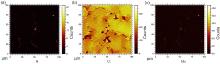
As shown in Fig. 1(a, b), particles of about several hundred nanometers precipitate along the grain boundary of the heat-treated IN792 superalloy. TEM-EDS analysis in Fig. 1(c) shows that these particles are enriched in Cr, Mo and W, which are consistent with the composition of carbide[16, 17] and boride[6, 8]. Since EDS is incapable of detecting boron and the contamination would make the carbon peak inaccurate, the EELS technique was used to analyze the particles and the detected boron peak is shown in Fig. 1(d), while the carbon peak is not found, which proves that the grain boundary particles are borides.
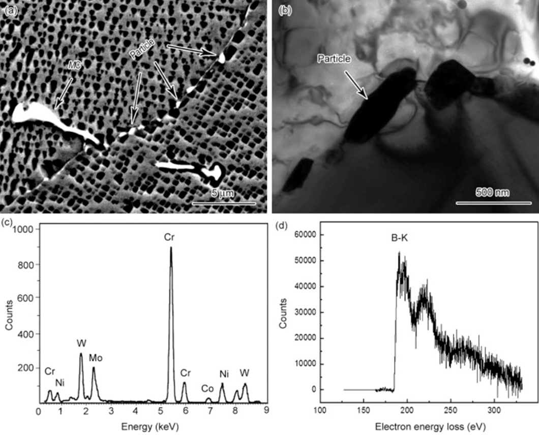 | Fig. 1. (a) SEM and (b) TEM images showing the particles precipitate along the grain boundary; (c) EDS spectrum of the particles; (d) background subtracted electron energy loss spectra showing the absorption edge of boron of the particles. |
SIMS is a surface analysis method with high detection sensitivity and resolution. It can detect a ppm order concentration of elements. Besides, it can detect light elements, which cannot be detected by other methods, such as H, B, O and C. IN792 superalloy contains trace amount of B which is hard to be detected by other methods. Thus SIMS technique was adopted to observe the distribution of boride. The boride found in the alloy is rich in Cr and Mo. As shown in Fig. 2, B, Cr and Mo are all concentrated along the grain boundary, which means that borides are distributed at the grain boundary.
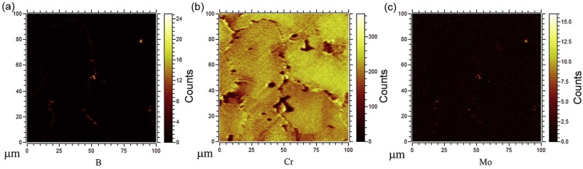 | Fig. 2. SIMS images showing the distribution of (a) B, (b) Cr and (c) Mo in IN792 alloy. |
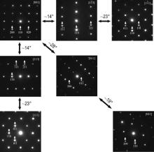
TEM electron diffraction analyses were performed to study the crystal structure of the borides and a group of selected area diffraction patterns (SADPs) obtained from a boride particle is shown in Fig. 3. Analysis of the electron diffraction patterns obtained from different zone axes indicates that the boride phase is M5B3 with a body-centered tetragonal structure, the lattice parameters of which are a = 0.57 nm, c = 1.08 nm and c/a = 1.89. The results are in accordance with investigations by Zhang et al.[7, 8].
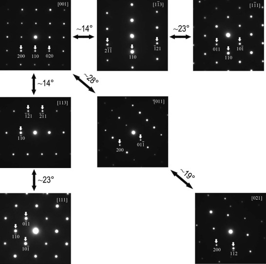 | Fig. 3. Group of SADPs of a boride particle obtained by tilting the crystal along certain crystallographic directions. |
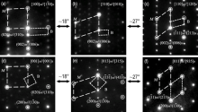
The orientation relationship between M5B3 phase and the matrix has been studied by other researchers [13, 14, 18]. For example, Huang et al.[14], Han et al.[18] and Sheng et al.[19, 20] have discovered a relationship of [001]γ /γ ′ //[001]M5B3[001]γ /γ ′ //[001]M5B3 betweenM5B3 phase and the matrix. Zhang and Ojo[13] showed that the orientation relationships between M5B3 phase and the matrix are [100]γ /γ ′ //[3$\overline{1}$0] M5B3, [010]γ /γ ′ //[130]M5B3[010]γ /γ ′ //[130]M5B3, [001]γ /γ ′ //[001]M5B3[001]γ /γ ′ //[001]M5B3. In this study, the crystallographic orientation relationship between theM5B3 phase and the matrix at one side of the grain boundary was further investigated and a special orientation relationship was found. As shown in Fig. 4(a-c), to tilt the crystal along(002)B(002)B, three orientation relationships can be obtained as follows:
[100]M//[1$\overline{3}$0]B, (002)M//(006)B, (020)M//(310)B(1)
[310]M//[010]B, (002)M//(006)B(2)
[110]M//[120]B, (002)M//(006)B, ($\overline{1}$11)M//(2$\overline{1}$3)B(3)
Moreover, the angles between the zone axes of orientation relationships in Eqs. (1) and (2), (2) and (3) are 18° and 27° , respectively.
Likewise, as demonstrated in Fig. 4(d-f), to tilt the crystal along (1$\overline{3}$0)B, another three orientation relationships can be obtained as
[001]M//[001]B, (200)M//(1$\overline{3}$0)B, (020)M//(310)B(4)
[013]M//[315]B, (200)M//(1$\overline{3}$0)B, ($\overline{1}$3$\overline{1}$)M//(43$\overline{1}$)B(5)
[011]M//[935]B, (200)M//(1$\overline{3}$0)B, (1$\overline{1}$1)M//(2$\overline{1}$$\overline{3}$)B(6)
The angles between the zone axes of orientation relationships in Eqs. (4) and (5), (5) and (6) are 18° and 27° , respectively. Therefore the angles among the three orientation relationships along (002)B(002)B in Fig. 4(a-c) are equal to that along (1$\overline{3}$0)B in Fig. 4(d-f).
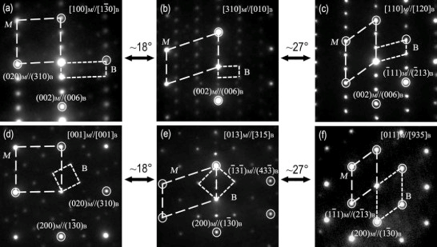 | Fig. 4. SADPs of the matrix and M5B3 phase showing the orientation relationships. (a-c) SADPs obtained from (a) [100]M//[1$\overline{3}$0]B, (b) [310]M//[010]B[310]M//[010]B, (c) [110]M//[120]B[110]M//[120]B along (002)B(002)B; (d-f) SADPs obtained from (d) [001]M//[001]B[001]M//[001]B, (e) [013]M//[315]B[013]M//[315]B, (f) [011]M//[935]B[011]M//[935]B along (1$\overline{3}$0)B. |
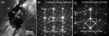
At the same time, two M5B3 phases are observed to co-exist in a single M5B3 particle as an intergrowth at the grain boundary besides existing alone, as shown in Fig. 5(a). The two M5B3 phases are marked as B1 and B2, respectively. The B1 and B2 boride exhibit quite different contrast in the intergrown M5B3 particle. It indicates that B1 and B2 have the same crystal structure, different crystal orientations. SADPs in Fig. 5(b, c) containing reflections from the matrix, B1 and B2, show a good orientation relationship between these three phases as follows:
[100]M//[1$\overline{3}$0]B1//[001]B2, (002)M//(006)B1//(1$\overline{3}$0)B2, (020)M//(310)B1//(310)B2(7)
[310]M//[010]B1//[315]B2, (002)M//(006)B1//(1$\overline{3}$0)B2(8)
 | Fig. 5. (a) TEM bright-field image of the intergrown M5B3 and γ matrix; (b, c) SADPs obtained from (b) [100]M//[1$\overline{3}$0]B1//[001]B2 and (c)[310]M//[010]B1//[315]B2[310]M//[010]B1//[315]B2 containing reflections from the matrix, B1 and B2. |
It has been reported that the addition of boron would significantly influence the grain boundary precipitation of nickel-based superalloys[8]. The size of boron atom is larger than that of the other interstitial atoms and smaller than that of the substitutional atoms in nickel-based superalloys[6], and thus the lattice distortion caused by boron is large. When the superalloy is aged at intermediate temperature, the boron tends to segregate to the grain boundaries. In addition, a large number of solute atoms, such as Cr and Mo, distribute at the grain boundaries. Since Cr and Mo are more inclined to dissolve in the matrix, when γ ′ phase is formed, Cr, Mo would be expelled and gather at the γ /γ ′ interface. As a result, B would interact with Cr and Mo and form M5B3 boride.
On the one hand, M5B3 borides dispersing at the grain boundary would pin the grain boundary and impede grain boundary sliding during creep. On the other hand, they would provide a discontinuous path for intergranular cracking. Therefore, they would improve the mechanical properties of superalloys.
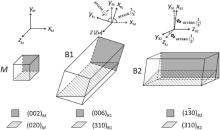
According to the orientation relationships shown in Fig. 5(b, c) and Eqs. (7) and (8), a schematic diagram of the crystalline lattice orientation of the matrix, B1 and B2, is drawn to demonstrate the orientation relationships intuitively, as shown in Fig. 6. The crystalline planes marked in gray and shadow in the schematic diagram show the orientation relationships in Fig. 5(a). The gray planes show the parallel relationship of (002)M//(006)B1//(1$\overline{3}$0)B2 and the shaded planes show the parallel relationship of (020)M//(310)B1//(310)B2(020)M//(310)B1//(310)B2.
 | Fig. 6. Schematic diagram of the crystalline lattice orientation of the matrix, B1 and B2. |
As can be seen from Fig. 6, the z-axis of B1 is parallel to the z-axis of the matrix; thus, (002)M(002)M shown in gray is parallel to(006)B1(006)B1. The x-axis and y-axis of B1 are anticlockwise tilted at an angle of arccot(1/3) relative to the x-axis and y-axis of the matrix. Therefore the shaded planes are parallel to each other, namely(020)M//(310)B1(020)M//(310)B1. While for B2, the z-axis of B2 is parallel to the x-axis of the matrix. The x-axis, y-axis of B2 are respectively anticlockwise tilted at an angle of arctan(1/3) relative to the y-axis, z-axis of the matrix. Therefore the gray planes in the matrix and B2 are parallel, namely (002)M//(13¯ 0)B2, and the shaded planes in the matrix and B2 are parallel, that is, (020)M//(310)B2(020)M//(310)B2. As the x-axis, y-axis and z-axis of the matrix are identical, it can be deduced that the orientation relationship between B1 and the matrix is the same as that between B2 and the matrix, even though the orientations of B1 and B2 are different.
In addition, as shown in Eq. (7), (310)B1 is parallel to (310)B2. Therefore the two [310] zone axes of B1 and B2 are parallel to each other, namely [310]B1//[310]B2[310]B1//[310]B2. As a result, B2 can be formed through rotating a certain angle around the [310] zone axis of B1. As [001] zone axis is perpendicular to [310] zone axis, the angle between [001]B1[001]B1 and [001]B2[001]B2 is the rotation angle. According to Fig. 6, we can see [001]B1//[001]M[001]B1//[001]M, [001]B2//[100]M[001]B2//[100]M. Therefore the rotation angle is 90° . Consequently, the crystalline lattice of B2 is formed through rotating 90° around the [310] zone axis of B1.
The formation of the intergrown M5B3 phase is caused by the special orientation relationship shown in Fig. 4. According to Fig. 4(a, d) and Eqs. (1) and (4), the orientation relationships, [100]M//[1$\overline{3}$0]B, [001]M//[001]B[001]M//[001]B, can be obtained. Since the matrix has a face-centered-cubic structure, [100]M[100]M and [001]M[001]M are identical. When [1$\overline{3}$0]and [001][001] of the twoM5B3 phases in the intergrowth, B1 and B2, are parallel to each other, the orientation relationships of [100]M//[1$\overline{3}$0]B1//[001]B2 in Fig. 5(b) and Eq. (7) would appear. According to the preceding analysis, the orientation relationships in Eqs. (2) and (5) are obtained through tilting the crystal along (002)B(002)B and (1$\overline{3}$0)B about 18° , respectively, from the orientation relationship in Eqs. (1) and (4). As shown in Fig. 6, (002)B1(002)B1 is parallel to (1$\overline{3}$0)B2. As a result, tilt the crystal along (002)B1(002)B1 and (1$\overline{3}$0)B2 about 18° from the orientation relationship in Eq. (7), the orientation relationships in Fig. 5c and Eq. (8) are formed. Likewise, it can be deduced that when the crystal tilted along (002)B1(002)B1 and (1$\overline{3}$0)B2 about 27° from the orientation relationship in Eq. (8), the following orientation relationship can be obtained:
[110]M//[120]B1//[935]B2, (002)M//(006)B1//(1$\overline{3}$0)B2, ($\overline{1}$11)M//(2$\overline{1}$3)B1//($\overline{3}$$\overline{3}$3)B2 (9)
The intergrowth phenomena of different phases have been discovered by many researchers, and the formation mechanism has been analyzed. For example, Ye et al.[21] have discussed the intergrowth structures of σ -related phases and the µ phase in an iron-based superalloy and explained the effect of microtwin bands and planar faults on the interphase boundary of the intergrowth structures. Tan et al.[22] have investigated the intergrowth of P phase with µ phase in a Ru-containing single-crystal Ni-based superalloy and indicated that P phase nucleates at stacking faults and subsequently grows at the expense of µ phase. Likewise, the previous studies about the intergrown borides are focused on different borides, or the same borides with different crystallographic structures. For example, Zhang and Ojo[6] have found that body-centered tetragonal (bct) and face-centered orthorhombic (fco) crystal structures of M2B can co-exist in a single M2B particle as an intergrowth. In their point, the formation of the intergrown M2B is due to the mutual transformation from one structure to the other by the introduction of planar defects, such as stacking faults. It can be concluded that the previous studies of the intergrowth always relate to the planar defects, for example, stacking faults and microtwins. However, the intergrowth of M5B3 phase in this study is distinct from these previous studies for the following reasons. First, the two parts of the intergrown M5B3 phase, B1 and B2, have the same crystallographic structure. Second, the formation of the intergrowth of M5B3 phase is independent of planar defects. Instead, it is due to the special orientation relationships between M5B3 phase and the matrix, as the preceding analysis.
The nucleation mechanism of the two parts of the intergrown M5B3 phase, B1 and B2, is still unclear at present. However, two possible mechanisms might be used as explanations, which are demonstrated in Fig. 7. The first one is that the two parts of the intergrown M5B3 phase, B1 and B2, nucleated individually at two close sites at the grain boundary, then got close to each other in the growth process, and finally formed an intergrown M5B3 phase, as indicated in Fig. 7(a). During aging process, B segregated at the grain boundary would interact with Cr and Mo, thus produce M5B3 cores. Two M5B3 cores, B1 and B2, are at two close sites. The orientation relationship between B1 and the matrix is: [001]B1//[001]M[001]B1//[001]M, [1$\overline{3}$0]B1//[100]M. The orientation relationship between B2 and the matrix is: [001]B2//[100]M, [1$\overline{3}$0]B2//[001]M. As B1 and B2 grow, the distance between them decreases. Finally, they encounter each other and become an intergrowth M5B3 phase. The second mechanism is that one M5B3 core forms and grows at the grain boundary, and then the other M5B3 core nucleates on it. Ultimately an intergrown M5B3 phase forms. The schematic diagram in Fig. 7(b) shows the whole process. B2 nucleates at the grain boundary and shows an orientation relationship with the matrix as: [001]B2//[100]M, [1$\overline{3}$0]B2//[001]M. As B2 grows, the distortion energy between the crystal lattices of B2 and the matrix increases. When the distortion energy reaches a certain value, B2 stops growing. At this time, the residual B, Cr, Mo would lead to the formation of B1. In order to reduce the distortion energy, B1 would connect to B2 with a low index crystal plane: (006)B1//(1$\overline{3}$0)B2, (310)B1//(310)B2. Besides, B1 shows a different orientation relationship with the matrix as: [001]B1//[001]M, [1$\overline{3}$0]B1//[100]M. Finally, B1 grows and the intergrown M5B3 phase forms.
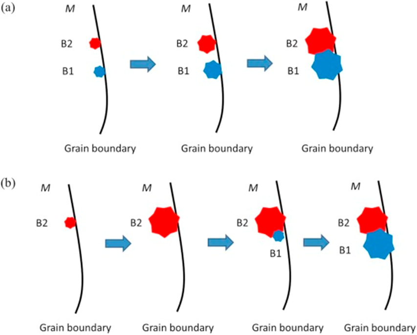 | Fig. 7. Schematic diagram of the intergrown M5B3 phase formation mechanisms: (a) B1 and B2 nucleate individually; (b) B1 nucleates on B2. |
(1)The precipitates of about several hundred nanometers at the grain boundaries of a heat-treated IN792 superalloy are M5B3 borides with a body-centered tetragonal structure, which would improve the mechanical properties of the superalloy.
(2)The M5B3 borides exhibit a special orientation relationship with the matrix at one side of the grain boundary.
(3)An intergrowth of two M5B3 phases, which have the same crystal structure and different crystal orientations, is found in a single M5B3 boride, thus form an orientation relationship between the two M5B3 phases and the matrix.
(4)The intergrowth of M5B3 phase is formed due to the special orientation relationship between M5B3 phase and the matrix.
(5)The two parts of the intergrown M5B3 phase, B1 and B2, can be formed by two mechanisms: one is that B1 and B2 nucleate individually and grow together. The other one is that B2 nucleates and grows first, and then B1 nucleates on B2.
This work was partly supported by the High Technology Research and Development Program of China (No. 2014AA041701), the National Natural Science Foundation of China (Nos. 51171179, 51271174, 51331005, and 11332010), and China Postdoctoral Science Foundation under Grant No. 2015M580923.
The authors have declared that no competing interests exist.
| [1] |
|
| [2] |
|
| [3] |
|
| [4] |
|
| [5] |
|
| [6] |
|
| [7] |
|
| [8] |
|
| [9] |
|
| [10] |
|
| [11] |
|
| [12] |
|
| [13] |
|
| [14] |
|
| [15] |
|
| [16] |
|
| [17] |
|
| [18] |
|
| [19] |
|
| [20] |
|
| [21] |
|
| [22] |
|