Comparative Study on Optical Properties and Scratch Resistance of Nanocomposite Coatings Incorporated with Flame Spray Pyrolyzed Silica Modified via in-situ Route and ex-situ Route
Yun Wang, Ling Zhang, Yanjie Hu, Chunzhong Li
Key Laboratory for Ultrafine Materials of Ministry of Education, School of Materials Science and Engineering, East China University of Science and Technology, Shanghai 200237, China
* Corresponding authors. Prof.; Tel.: +86 21 64250949; Fax: +86 2164250624.E-mail addresses: zlingzi@ecust.edu.cn (L. Zhang); czli@ecust.edu.cn (C. Li).
Abstract

A new type of transparent scratch resistant coatings including in-situ modified SiO2 (g-SiO2) in flame spray pyrolysis (FSP) process was prepared. The maximum content of g-SiO2 in the coating was 15 wt%, which is higher than that of SiO2 modified by traditional wet chemical route (l-SiO2, only 10 wt%). The results of transmission electron microscopy have demonstrated that in-situ surface modified g-SiO2 particles dispersed well with smaller agglomerates in the final coating, which was much better than the particles modified via wet chemical route. Visible light transmittance and haze tests were introduced to characterize the optical quality of the films. All coatings were highly transparent with the visible light transmittance of above 80%, especially for coatings containing g-SiO2, which exhibited slightly higher visible light transmittance than l-SiO2 embedded one. The haze value of coatings incorporated with 15 wt% g-SiO2 was 1.85%, even lower than the coating with 5 wt% l-SiO2 (haze value of 2.09%), indicating much better clarity of g-SiO2. The excellent optical property of g-SiO2 filled coatings was attributed to the good dispersion and distribution of particles. Nano-indention and nano-scratch tests were conducted to investigate the scratch resistance of coatings on nano-scale. The surface hardness of the coatings rose by 18% and 14%, and the average friction coefficient decreased by 15% and 11%, respectively, compared to the neat coat due to the addition of 10 wt% g-SiO2 and l-SiO2. The pencil hardness of the coating with 15 wt% g-SiO2 increased from 2B for the neat coating to 2H. However, the pencil hardness of coating with 10 wt% l-SiO2 was only H. The results showed that the g-SiO2 embedded coatings exhibited higher scratch resistance and better optical properties.

Keyword: In-situ modification; Silica; Coating; Scratch resistance; Optical property
1. Introduction

With the advantages of efficient processing, low weight and excellent optical quality, transparent polymers, for example polycarbonate (PC), polymethylmethacrylate (PMMA), and polystyrene (PS), are widely used for windows, lenses and other devices. However, the weak surface mechanical properties of these polymers make them deteriorate easily, imposing a problem for their durability[1, 2, 3]. A number of researches are targeted to improve the scratch resistance of the organic coatings. One attractive and efficient way is to combine the flexibility of organic coatings with the hardness of inorganic fillers[4, 5]. A variety of nanofillers have been studied, such as nano-silica (SiO2)[6, 7, 8, 9, 10, 11], nano-alumina (Al2O3) [12, 13], nano-titania (TiO2)[14], nanotubes and clay[15].

High load of nanofillers is typically favorable for enhancing the scratch resistance of composite coatings. Unfortunately, it normally leads to declined optical qualities for most of these nanofillers. Much attention has been focused on SiO2 embedded coatings due to its matchable refractive index (RI) to most organic coatings. According to Zhang et al.[16], pyrogenic silica particles present higher mechanical properties compared to colloidal particles, resulting in higher coating scratch resistance. However, the pyrogenic silica particles tend to aggregate in organic coatings, resulting in poorer optical properties. Salleh et al.[17] compared the effect of monomers, prepolymers and nano-SiO2 on the scratch resistance of nano-composite coatings; the viscosity of coatings increased with increasing nanosilica content, which limited the maximum loadings of nano-silica. It is well known that the dispersion state of nano-fillers and the interaction between fillers and coating matrix play a critical role in determining the optical properties and the scratch resistance of the coatings. Therefore, the surface modification of SiO2 by attaching appropriate organic compounds is required to be hydrophobic[18].

Traditional surface modification method includes multiple-step processes, introducing first the reactive groups such as C=C and subsequently the coating and/or surface modification. Recent work by Teleki et al.[19] provided a facile and fast process of in-situ organic surface modification of flame-made nanoparticles by spraying modifying agent solution directly into freshly prepared nanoparticles. The modifier can graft onto TiO2 particle surfaces instantly. Compared to traditional multiple-step processes, this method is superior in convenience and low cost, and it gives a potential advantage of obtaining low extent of nanoparticle aggregation. However, only few researches have been carried out on gas-phase in-situ surface functionalization.

Herein, we developed a new type of transparent scratch resistant coatings with continuous gas-phase in-situ modified SiO2 (g-SiO2). SiO2 nanoparticles are made by flame spray pyrolysis (FSP) process and functionalized by in-situ spraying precursor solution of 3-methacryloxypropyltrimethoxyl silane (MPS) molecules into the fresh SiO2 stream. The MPS molecules with C=C bonds and methoxy groups can not only be anchored onto the surface of SiO2 but also participate in reaction with coat matrix through covalent bonds when photo-curved. The objective of this work is to investigate the effect of the g-SiO2 on scratch resistance and optical qualities of the final composite coatings, compared to SiO2 modified by traditional wet chemical route (l-SiO2). The results showed that in-situ surface modification in FSP process shows a unique advantage on the fabrication of high-performance nanocomposites with well-dispersed and distributed nanofillers, possessing a promising development potential.

2. Experimental
2.1. Raw materials

Tetraethyl orthosilicate (TEOS) was obtained from Shanghai Lingfeng Chemical Reagent Co., Ltd. 3-methacryloxypropyltrimethoxyl silane (MPS) was received from Sinopharm Chemical Reagent Co., Ltd. The commercial hexa-functional aliphatic urethane-acrylate (UA) oligomer named as “ Ebecryl 1290” and trimethylolpropane tris-acrylate (TMPTA) serving as reactive diluent were supplied by Cytec Industries Inc. The photo-initiator 1-hydroxy-cyclohexyl phenyl ketone (Irgacure 184) was provided by Ciba Specialty Chemicals. A commercially available nano-SiO2 named as Aerosil® R 7200 with a primary particle size distribution in the range of 13-50 nm was kindly supplied by Evonik Degussa GmbH. All the materials in this study were used as received without further purification.

2.2. Methods

2.2.1. In-situ modification of FSP-SiO2

The in-situ modification of SiO2 was carried out in a modified flame FSP reactor. An illustration of the experimental reactor is shown in Fig. 1. FSP burner was enclosed by a 45-cm long tube with 5-cm inner diameter, above which a 5-cm long tube with 12 internal section outlets (1 mm i.d. each) was placed, through which flowed cooling air (0.5 m3/h). Another 15-cm long tube with a side branch was placed above the cooling tube. An internal gas-assist nozzle (i.d. = 1 mm, 60 cm above the FSP burner) was put into that side tube, spraying 3 mL/min of MPS solution dispersed by 0.25 L/min N2 at 1.5 × 10⁵ Pa (1.5 bar) pressure drop (45° from the vertical) into the tube. Finally a 30-cm long tube for surface modification of silica was presented. The final products were collected by filter cloth.

Fig. 1. Illustration of experimental reactor for in-situ surface modification of FSP-made SiO2

The TEOS solution in ethanol (0.5 mol/L) was fed at 3 mL/min into the FSP burner and dispersed into drops by O2 (0.3 m3/h) with 1.0 × 10⁵ Pa (1.0 bar) pressure drop at the nozzle tip. The MPS solution in ethanol/water (9:1 by volume, 0.04 mol/L, pH = 4.5) was pre-activated at 60 ° C for 1 h to ensure complete hydrolyzation of MPS. Hydrophobic SiO2 was prepared by spraying MPS solution (3 mL/min) directly into the freshly formed hydrophilic SiO2 particles.

2.2.2. Ex-situ modification of FSP-silica

For comparison, ex-situ modified SiO2 was synthesized by means of wet chemistry route. The pure SiO2 was prepared by direct spraying TEOS solution into fame reactor, under the same condition as g-SiO2 without spraying MPS solution. The ex-situ surface modification was performed as follows: 2.0 g of as-prepared pure SiO2 was dispersed into 200 mL solution of ethanol and water (94.5:5.5 by volume) via sonication for 30 min. Acetic acid was added to adjust the pH value of the solution to 4.5. 0.2 g MPS (10 wt% of pure SiO2) was gradually added to the dispersed solution, and the solution was stirred at 65 ° C for 24 h. Finally, the suspension was centrifuged and washed with ethanol for 3 times and dried.

2.2.3. Coating formulation and film preparation

Three types of SiO2 were introduced in the nanocomposite coatings: the hydrophobic SiO2 in-situ FSP-modified by MPS (marked as g-SiO2), the SiO2 ex-situ treated in ethanol/water by MPS (marked as l-SiO2), and the hydrophobic pyrogenic SiO2 named as Aerosil® R7200 (marked as r-SiO2) for comparison.

Proper amount of SiO2 nanopowder was added into TMPTA, followed by stirring and sonication for 1.5 h with ultrasonic cell disruptor. The resultant clear blends were used as the masterbatch in the following step. Because of residual-OH groups on the surfaces of SiO2, the viscosity of the masterbatch increases dramatically with the content of SiO2, causing great difficulty in later operation. Maximum filler content existed for these masterbatches: 25 wt% for g-SiO2 and 20 wt% for l-SiO2. Further increase of nanosilica content was impractical for processing. Masterbatch of r-SiO2 with 25 wt% particle content was also prepared for comparison.

The SiO2 masterbatch was added with proper amount of UA and TMPTA to obtain dispersions with varying SiO2 contents. The compositions of all the mixtures produced are outlined in Table 1 The amount of the photoinitiator remained constant and equal to 4 wt% of the mixture. After addition of the photoinitiator, the dispersions were intensively stirred and degassed under reduced pressure and then spin-coated onto PC substrates (1.5 mm in thickness) at a rotation speed of 900 rpm for 6 seconds and 1800 rpm for 15 seconds. All PC plates were washed with ethanol before use. The wet films were subsequently UV-cured for 180 seconds using a hot embossing system equipped with UV unit, with the UV light intensity of about 1.5 mW/cm2 at a wavelength of 365 nm. The thickness of the coatings is in the range of 40-50 µ m. For simplicity, “ 15g-SiO2” represents the coating with 15 wt% g-SiO2.

Table 1. Compositions of coating samples with various nano-silica contents
2.3. Characterization

Thermogravimetric analysis (TGA) was taken by TGA/SDTA851e analyzer from room temperature to 800 ° C with a heating rate of 10 ° C/min under nitrogen. Transmission electron microscopy (TEM) images were directed by a JEM-1400 with in-column filter at 120 kV of acceleration voltage type transmission electron micrograph. The specific surface area (SSA) of silica was determined using a surface area and porosity analyzer (ASAP 2010N) by Brunauer-Emmett-Teller (BET).

The nano-indentation test was conducted on a TriboIndenter system (standard diamond Berkovich tip, triangular pyramid shape and curvature radius of 200 nm). A constant maximum penetration load of 10 mN was chosen for all samples. The applied load was controlled according to a pre-determined loading function, which consists of a 20-s linear loading to 10mN, followed by a 5-s dwelling, and finally a 20-s linear unloading. The displacement of indenter was monitored during the loading and unloading process.

The nano-scratch test was also carried out; a conical diamond tip of 60° cone angle was used. A pre-scan was performed on a 15 µ m × 15 µ m square area to get the initial topography of the sample. The load applied on the tip increased linearly to 0.8 mN in 5 s, maintained for 3 s, and then moved the tip by 10 µ m in 30 s, maintained for 3 s, and finally decreased the normal load to 0 mN in 5 s. The displacement of the indenter was constantly monitored during the test. At last, the post-scan was performed on the worn sample surface through the image processing process.

The pencil hardness of coatings on the PC plate was tested according to the standard GB/T 6739-1996. The visible light transmittance of the coatings was measured by a UV-vis-NIR scanning spectrophotometer (CARY 500) over a range of 300-800 nm. The worn surfaces of the nano-coatings were examined by optical microscopy. The haze values of the coatings were determined using a haze meter (WGT-S, Shanghai Precision and Scientific Instrument) according to GB/T 2410-2008.

3. Results and Discussion
3.1. Comparison of in-situ and ex-situ modified FSP-silica

TGA curves of g-SiO2 and l-SiO2 are shown in Fig. 2(a). The obvious weight loss in the range of 300-600 ° C was attributed to thermal decomposition of organic MPS molecules. By comparison of the curves, higher grafting content of 8.6 wt% was presented for g-SiO2 than l-SiO2 of 2.8 wt%. Full hydrolyzation of MPS in ethanol/water before spraying and high grafting temperature helped to obtain higher grafting content of g-SiO2. The g-SiO2 exhibited strong hydrophobic property than l-SiO2 (the inset in Fig. 2 (a)). The TEM pictures of SiO2 particles are shown in Fig. 2 (b). The g-SiO2 particles dispersed well in acetone and exhibited typical network structure. While for l-SiO2, the network structure was destroyed, l-SiO2 particles dispersed in small aggregations. Direct surface modification of freshly formed silica particles in in-situ process could avoid further aggregation to a certain extent, which gives this process the advantage of obtaining fine dispersion of silica particles in organic solvent. The SSA of pure flame-made SiO2 was 192 m2/g and reduced to 111 m2/g after in-situ modification due to the present of MPS on the surface.

Fig. 2. Characterization of SiO2 particles: (a) TG results of g-SiO2 and l-SiO2 particles (the inset: the hydrophobic property test); (b) TEM pictures of g-SiO2, l-SiO2 and pure SiO2 in acetone.

3.2. Comparison of optical properties of nanocomposite coatings

3.2.1. Visible light transmittance

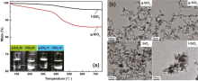
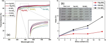
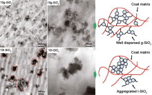
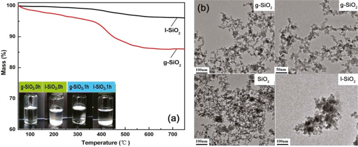
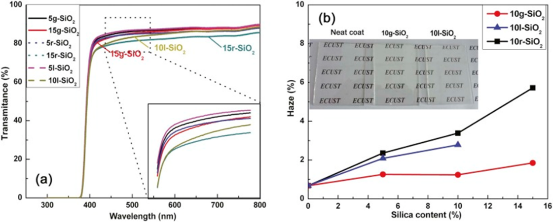
Transparency of the films presents a key parameter for the use of the prepared coatings. The transparency of coatings with comparable thickness in the range from 30 to 40 µ m was characterized by UV-vis spectrophotometry (Fig. 3(a)). All films loaded with nano-silica were highly transparent. The light transmittance decayed obviously with increasing content of l-SiO2, while in the case of g-SiO2, the addition of g-SiO2 hardly reduced the visible light transmittance of coatings even with 15 wt% silica, which is different from the behavior of traditional flame-made SiO2 reported in the literature[16]. In fact, g-SiO2 and l-SiO2 were obtained from the same silica (FSP-made SiO2) and modifier (MPS), and therefore, it can be assumed that the variations in optical transmittance arise from their difference in modification process rather than other factors. Fig. 4 shows the TEM images of SiO2 nanocomposite coatings. It can be easily observed that the dispersion state of g-SiO2 was notably different from l-SiO2. l-SiO2 particles aggregated severely with the aggregation size of even 200-400 nm in coat matrix, whereas g-SiO2 dispersed homogeneously on nanoscale without large aggregations. Large size of aggregations of nano-fillers in coatings causes significant light-scattering, declining the coating optical transparency. In-situ FSP modified SiO2 exhibited advantage in obtaining homogeneous filler dispersion in coatings over ex-situ treated one, which plays a great role in optical transparency.

Fig. 3. Optical qualities of coatings: (a) optical transmittance of coatings; (b) haze values (the inset: the digital photos of neat coating (left), 10 wt% g-SiO2 coating and 10 wt% l-SiO2 coating (right)). In a typical example for simplicity, “ 15g-SiO2” represents the coating with 15 wt% g-SiO2.

Fig. 4. TEM images and schematic illustrations of dispersion state of silica in composite coatings embedded with 10 wt% g-SiO2 and 10 wt% l-SiO2.

3.2.2. Haze values

The haze values can be used to evaluate the clarity of transparent coatings. As shown in Fig. 3(b), g-SiO2 loaded coating gave the lowest haze values among all films, and the haze values tended to be insensitive to the content of SiO2, which is also different from the observation reported elsewhere[16]. For l-SiO2 and r-SiO2 samples, the haze value increased significantly with SiO2 content. With the SiO2 content of 15 wt%, the haze value was 1.85% for g-SiO2 nanocomposite coating, while it increased to 5.72% for r-SiO2. The haze value of l-SiO2 coating with only 10 wt% filler was 2.78%, higher than g-SiO2 coating with 15 wt% silica. The advantage of in-situ FSP modification in the haze of nano-coatings can be attributed to the same reason described in optical transmittance measurement. Higher grafting content of MPS on SiO2 for g-SiO2 facilitates the dispersion of g-SiO2 and stronger interfacial interaction[20] and [21], thus providing lower haze value of final coatings.

3.3. Comparison of scratch resistance of nanocomposite coatings

3.3.1. Nano-indentation measurement

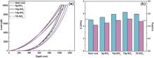
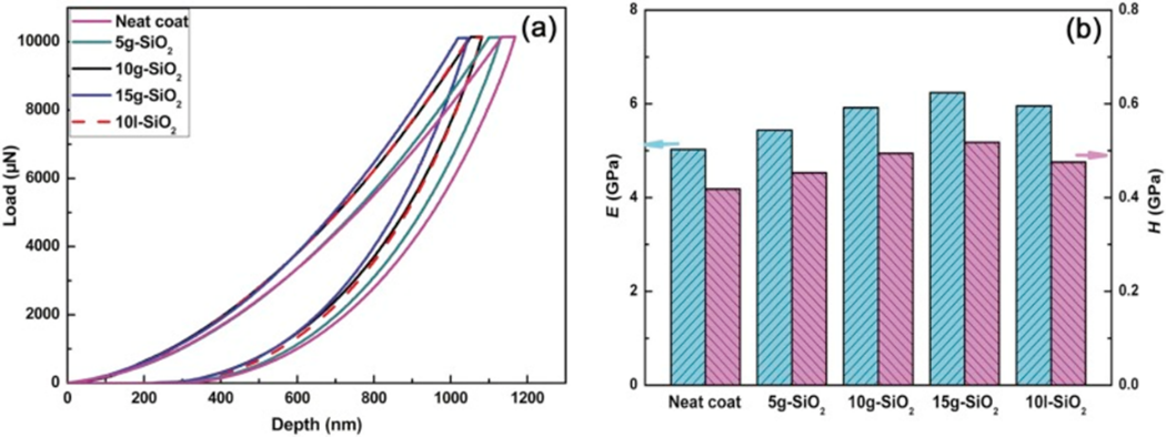
Nano-indentation test is an effective technique in characterizing surface mechanical properties of thin films or coatings[22]. The typical loading-unloading curves of neat coating and coatings filled with 10 wt% g-SiO2 or 10 wt% l-SiO2 are shown in Fig. 5(a). The surface hardness (H) and elastic modulus (E) of the coatings obtained from the Oliver and Pharr methodology are given in Fig. 5(b)[23].

Fig. 5. Loading-unloading curves of coatings (a) and corresponding surface mechanical properties (b) in nano-indention test.

As presented in Fig. 5(a), the maximum indentation depth of neat coating is about 1167 nm under the maximum load of 10 mN, and it decreased to around 1069 nm and 1080 nm for coatings with 10 wt% g-SiO2 and 10 wt% l-SiO2, respectively, indicating that the incorporation of inorganic SiO2 particles enhanced the coating resistance to the penetration by the indenter, and g-SiO2 composite coating exhibited slightly higher penetration resistance than l-SiO2 filled one. In comparison to the maximum indentation depth above 1000 nm, all three coatings showed much lower residual depth, around 300 nm. The addition of nano-SiO2 hardly decreased the recovery ability of the coating matrix. Actually the percentage of elastic recover (Re) of g-SiO2 coating increased slightly in comparison to neat coating and l-SiO2 composite coating. As shown in Fig. 5(b), both coating hardness and modulus could be enhanced with the incorporation of nano-SiO2. At the filler content of 10 wt%, the surface hardness rose from 418 MPa for neat coating to 494 and 475 MPa for g-SiO2 and l-SiO2 filled coatings, respectively, and elastic modulus from 5.02 GPa to 5.91 and 5.95 GPa; SiO2 particles made the coating much stiffer.

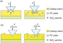
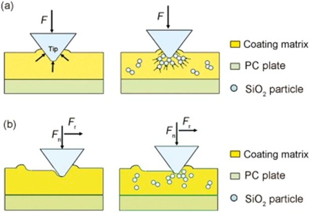
Scheme illustration of indentation test is presented in Fig. 6(a). It is recognized that the mechanical properties of nano-fillers and the interface combination play a great role in the final composite performance. The hardness and modulus of nano-SiO2 are much higher than those of the coating matrix, thus enhancing the hardness and modulus of composite coatings. Moreover, modified SiO2 could act as a load-transferring agency, which could effectively enhance the maximum standing load applied on the coating, thereby increasing the ability against indentation. It could also be seen in Fig. 5 that the g-SiO2 composite coating exhibited higher indentation hardness than l-SiO2 composite coating at the filler content of 10 wt%. As previously proven, the MPS grafting content of g-SiO2 is much higher than that of l-SiO2, indicating that more MPS molecules could connect silica with the coating matrix at the interfaces after photo curved. When being indented, a better load transference effect could occur in g-SiO2 embedded coating, offering higher indentation hardness.

Fig. 6. Illustration of indentation (a) and scratch (b) test on neat coating and silica-loaded coating.

3.3.2. Nano-scratch measurement

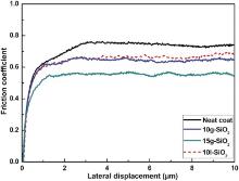
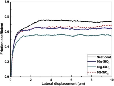
The scratch resistance of composite coatings can be estimated by friction coefficient in nano-scratch test (Fig. 7). It can be seen that the average friction coefficient of neat coating and coatings with 10 wt% g-SiO2 and 10 wt% l-SiO2 are 0.74, 0.63 and 0.66, respectively. Here the average friction coefficient was taken from the stable stage of the friction coefficient curves. About 15% decrease in average friction coefficient was achieved for coatings with g-SiO2, and 11% decrease for coatings with l-SiO2.

Fig. 7. Friction coefficient curves of the coatings in nano-scratch test.

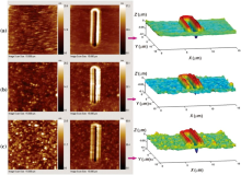
The worn surfaces of coating samples are presented in Fig. 8. The residual depths were much lower than penetration depths (not shown), which can be attributed to the deformation recovery of the coatings. The g-SiO2 hybrid coating gives the lowest residual depth, indicating the best scratch resistance on nanoscale. The SiO2 filler enhanced the scratch resistance of the coatings, and g-SiO2 offered a slightly better enhancement than l-SiO2. Besides, the surface morphologies of the films after SiO2 incorporation were also changed, as observed in Fig. 8. The neat film is almost smooth, and the incorporation of SiO2 causes the surface roughness of the films to increase. The bright spot in the images of SiO2 embedded coatings resulted from the aggregation of SiO2 in the vicinity of coat surface. The coating filled with l-SiO2 was rougher than g-SiO2 composite coating, which could be explained from the severe aggregation of l-SiO2 in the coating revealed in Fig. 4.

Fig. 8. Worn surfaces of the coating samples before and after nano-scratch test: (a) neat coating, (b) with 10 wt% g-SiO2 nanoparticles, and (c) with 10 wt% l-SiO2 nanoparticles.

The illustration of nano-scratch test is presented in Fig. 6(b). As concluded in nano-indentation test, the addition of silica particles make the coatings harder, which accordingly means lower indentation depth and smaller contact area, so the real contact area decreases; besides, as shown in Fig. 8, the roughness of the coating increases after adding silica particles, the hump resulting from the existence of silica could prevent the scratch tip from contacting with more flatter coating surface. As a result, the coatings filled with silica particles present lower friction coefficient. The g-SiO2 composite coating gives higher indentation hardness in comparison with l-SiO2 coating, which means smaller contact area of coating surface and indenter; as a result, g-SiO2 composite coating shows lower friction coefficient.

3.3.3. Pencil hardness

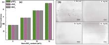
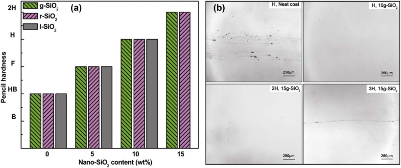
The scratch hardness of the cured coatings was also measured by pencil hardness test; the results are reported in Fig. 9(a). For better comparison, r-SiO2 was also presented. The pencil hardness was HB for neat coating, and it greatly enhanced to 2H for coating with 15 wt% g-SiO2 and 15 wt% r-SiO2. Because of dramatically increased coating viscosity for l-SiO2, the maximum content of l-SiO2 was 10 wt%, with the highest pencil hardness of H. The pencil hardness showed significant improvement with increasing nano-SiO2 content for all three types of coatings. The improvement of scratch hardness can be attributed to the increase of coating modulus and load-transferring effect due to the presence of the hard modified silica nanoparticles[20]. Besides, the strong interconnection of modified SiO2 with coating matrix might prevent the cracks from propagating when being scratched, which helped to improve the scratch resistance. For these three kinds of silica particles, at the same particle content, the nanocomposite coatings exhibited the same value of pencil hardness; different surface modifications of nano-silica did not affect the pencil hardness values greatly.

Fig. 9. Pencil hardness of the coating samples as a function of the nano-silica content (a) and worn surfaces of coatings after pencil hardness test (b).

The worn surfaces after pencil hardness test are shown in Fig. 9(b). The neat coating showed severe worn surfaces with numerous grooves after H grade pencil scratched. Comparatively, the nanocomposite films loaded with 10 wt% g-SiO2 or 10 wt% l-SiO2 presented smooth surface without grooves, indicating improved scratch hardness. When the content of silica increased to 15 wt% for g-SiO2, the nanocomposite coating can stand 2H grade pencil without grooves.

4. Conclusions

In summary, the unique advantage of in-situ surface modification method in flame spray pyrolysis process on fabrication of transparent scratch-resistant nanocomposite coatings was discussed. The composite coatings embedded with in-situ modified flame-spray pyrolyzed silica (g-SiO2) possesses stronger scratch resistance and higher transparency due to their better filler dispersion and distribution, compared to the coatings embedded with traditional ex-situ modified silica (l-SiO2). In detail, the following points can be summarized:

(1)Higher maximum filler content in composite coating could be obtained for g-SiO2 due to its relatively lower coating viscosity compared to l-SiO2.

(2)The in-situ surface modification process offered g-SiO2 better dispersion state in coatings compared to ex-situ modified silica, which plays a quite important role in optical qualities and scratch resistance of the film.

(3)In comparison with l-SiO2, much lower haze value and slightly higher visible light transmittance were observed for g-SiO2 embedded coatings at the same particle content. The haze value of composite coating with 15 wt% g-SiO2 was 1.85%, even lower than that of the film with 5 wt% l-SiO2 (haze value of 2.09%).

(4)The addition of the two modified silica definitely improved the scratch resistance of coatings. Compared to the neat coat, the surface hardness of the coatings rose by 18% and 14%, and elastic modulus rose by 18% and 19% for coatings with 10 wt% g-SiO2 and 10 wt% l-SiO2, respectively. Composite coatings incorporated with g-SiO2 exhibited higher scratch resistance on nanoscale.

(5)Similar enhancement of scratch resistance on macro-scale was observed for coatings with g-SiO2 and l-SiO2 at the same filler content. The pencil hardness of the coating with 15 wt% g-SiO2 increased from 2B for the neat coat to 2H, and coating with 10 wt% l-SiO2 to H.

Acknowledgements Acknowledgments:

This work was supported by the National Natural Science Foundation of China (Nos. 51173043, 21236003, and 21322607), the Basic Research Program of Shanghai (Nos. 13JC1408100 and 15JC1401300), the Key Scientific and Technological Program of Shanghai (No. 14521100800), and the Fundamental Research Funds for the Central Universities.

The authors have declared that no competing interests exist.

Reference
[1] C. Charitidis, A. Laskarakis, S. Kassavetis, C. Gravalidis, S. Logothetidis, Superlattices Microstruct. 36(2004) 171-179. [本文引用:1]
[2] L. Y. L. Wu, E. Chwa, Z. Chen, X. T. Zeng, Thin Solid Films 516 (2008) 1056-1062. [本文引用:1]
[3] M. Sangermano, M. Messori, Macromol. Mater. Eng. 295(2010) 603-612. [本文引用:1]
[4] E. Scrinzi, S. Rossi, P. Kamarchik, F. Deflorian, Prog. Org. Coat. 71(2011) 384-390. [本文引用:1]
[5] S. W. Chen, B. You, S. X. Zhou, L. M. Wu, J. Appl. Polym. Sci. 112(2009) 3634-3639. [本文引用:1]
[6] R. Saito, S. I. Kobayashi, H. Hayashi, T. Shimo, J. Appl. Polym. Sci. 109(2008)1498-1504. [本文引用:1]
[7] F. Bauer, R. Flyunt, K. Czihal, M. R. Buchmeiser, H. Langguth, R. Mehnert, Macromol. Mater. Eng. 291(2006) 493-498. [本文引用:1]
[8] Z. Z. Wang, P. Gu, X. P. Wu, H. Zhang, Z. Zhang, M. Y. M. Chiang, Compos. Sci. Technol. 79(2013) 49-57. [本文引用:1]
[9] M. M. Jalili, S. Moradian, H. Dastmalchian, A. Karbasi, Prog. Org. Coat. 59(2007)81-87. [本文引用:1]
[10] T. Mizutani, K. Arai, M. Miyamoto, Y. Kimura, Prog. Org. Coat. 55(2006) 276-283. [本文引用:1]
[11] A. Dashtizadeh, M. Abdouss, H. Mahdavi, M. Khorassani, Appl. Surf. Sci. 257(2011) 2118-2125. [本文引用:1]
[12] D. Hosseinpour, J. T. Guthrie, J. C. Berg, Prog. Org. Coat. 62(2008) 214-218. [本文引用:1]
[13] L. P. Sung, J. Comer, A. M. Forster, H. Q. Hu, B. Floryancic, L. Brickweg, R. H. Fernand o, J. Coat, Technol. Res. 5(2008) 419-430. [本文引用:1]
[14] F. Bondioli, M. E. Darecchio, A. S. Luyt, M. Messori, J. Appl. Polym. Sci. 122(2011)1792-1799. [本文引用:1]
[15] L. Fogelstrom, E. Malmstrom, M. Johansson, A. Hult, Appl. Mater. Interfaces 2(2010) 1679-1684. [本文引用:1]
[16] H. Zhang, L. Tang, L. Zhou, C. Eger, Z. Zhang, Compos. Sci. Technol. 71 (4) (2011)471-479. [本文引用:3]
[17] N. G. N. Salleh, M. F. Yhaya, A. Hassan, A. A. Bakar, M. Mokhtar, Int. J. Polymer. Mater. 58(2009) 422-451. [本文引用:1]
[18] H. Zou, S. S. Wu, J. Shen, Chem. Rev. 108(2008) 3893-3957. [本文引用:1]
[19] A. Teleki, N. Bjelobrk, S. E. Pratsinis, Langmuir 26 (2010) 5815-5822. [本文引用:1]
[20] M. Rostami, M. Mohseni, Z. Ranjbar, Int. J. Adhes. Adhes. 34(2012) 24-31. [本文引用:1]
[21] H. I. Hsiang, Y. L. Chang, C. Y. Chen, F. S. Yen, Mater. Chem. Phys. 120(2010)476-479. [本文引用:1]
[22] Y. Bautista, J. Gonzalez, J. Gilabert, M. J. Ibanez, V. Sanz, Prog. Org. Coat. 70(2011)178-185. [本文引用:1]
[23] W. C. Oliver, G. M. Pharr, J. Mater. Res. 7(1992) 1564-1583. [本文引用:1]