Considering the compatibility between degradation and bioactivity of magnesium-based implants for bone repair, micro-arc oxidation is used to modify the magnesium alloy surface in aqueous electrolytes, allowing strontium, calcium, and phosphorus to be incorporated into the coating. The thickness, composition, morphology and phase of this Sr-Ca-P containing coating are characterized by scanning electron microscopy equipped with energy dispersive X-ray spectrometer and X-ray diffraction. The in vitro and in vivo degradation of the coating is evaluated by immersion test, electrochemical test and implantation test. Moreover, the cytocompatibility is tested with osteoblast cell according to ISO 10993. The results show that Sr, Ca and P elements are incorporated into the oxide coating, and a refined structure with tiny discharging micro-pores is observed on the surface of the coating. The Sr-Ca-P coating possesses a better corrosion resistance in vitro and retards the degradation in vivo. Such coating is expected to have significant medical applications on orthopedic implants and bone repair materials.
In recent years, magnesium-based biodegradable implants have attracted more attention in the fields of orthopedics[1, 2]. Magnesium and its alloys degrade relatively safely in the human body[3, 4], which avoids the removal of implants after healing. Magnesium has an essential role in human metabolism[5, 6], stimulates the growth of bone cells and promotes bone tyear healing[7, 8]. In addition, the specific strength and the similarity of Young's modulus of biodegradable Mg alloys to that of natural bone[9] reduce the risk of stress shielding in orthopedic applications. However, the initial rapid degradation leads to the loss of mechanical integrity and hydrogen evolution, which can retard the bone growth by acting as a physical barrier[10]. Thereby, the surface modification has been adopted to solve this limitation.
Micro-arc oxidation (MAO) is a promising technology to produce porous and firmly adherent coatings on substrates[11]. It has been intensively investigated as a class of biomedical coatings on magnesium alloys in recent years due to the better corrosion resistance, abrasion resistance and bioactivity[12]. The MAO technique can be used to control surface properties, such as oxide thickness, chemical composition, pore size, and roughness[13]. Previous studies indicated that the MAO coating could effectively control the degradation of magnesium matrix by in vitro and in vivo experiments[8, 14]. Moreover, the electrolyte solution containing bioactive elements, such as calcium, phosphate and silicon, has been developed to enhance the biological compatibility and activity of MAO coatings for magnesium and its alloys[14, 15, 16]. Wang et al.[8] fabricated a bioactive Ca-P containing MAO coating on pure magnesium in an electrolyte solution consisting of calcium hydroxide, sodium hexametaphosphate and potassium fluoride. The results showed that this coating possesses excellent bioactivity and significantly retarded the degradation of magnesium substrate in vitro and in vivo with a great potential for orthopedic application.
Strontium (Sr) has been recently reported for its use in medical applications[17, 18, 19]. Sr is a natural bone-seeking trace element that accumulates in the skeleton[20]. There are a growing number of evidence that Sr influences bone remodeling by affecting both bone resorption and bone formation[19]. Recently, some novel biomaterials such as strontium-substituted calcium phosphates and a series of Sr containing magnesium alloys have been developed to improve the biocompatibility of the implants[21, 22, 23]. Several studies have shown that strontium containing hydroxyapatite (Sr-HA) is a bioactive bone cement that promotes osteoblast attachment and mineralization in vitro and bone growth and osteointegration in vivo[23]. Liu et al.[24] designed the Mg-Sr alloys as bone graft substitutes and proved that Mg-1.5 wt% Sr alloy possessed a predominant combination of degradation performance, high strength and biocompatibility compared with traditional filling materials. Additionally, Capuccini et al.[25] employed pulsed-laser deposition to prepare Sr-HA coating on titanium substrates. The presence of strontium in the coating enhanced osteoblast activity and differentiation, whereas it inhibited osteoclast production and proliferation.
Considering the beneficial effects as mentioned above, it is believed that the presence of Sr via a calcium phosphate coating will promote bone formation, enhance osteointegration, and ensure the slow degradation of magnesium-based implant. Therefore, it can achieve the demands of clinical bone repair. In this work, MAO was used to modify the magnesium strontium alloy surface in aqueous electrolytes in which strontium, calcium, and phosphorus were incorporated into the coating. The properties of the coating such as morphology, chemistry, corrosion resistance and also in vitro cytocompatibility were then evaluated. In vivo assessment of the Sr-Ca-P contained MAO coating was explored to evaluate the degradation and its influence on the bone tyear.
2. Materials and Methods
2.1. Materials
The Mg-1.5 wt% Sr alloy was studied in our previous work[24]. The as-cast ingots were cut into pieces with dimensions of Φ 10 mm × 2 mm. All samples were ground with 240#, 800#, 1200# and 2000# abrasive paper gradually, followed by ultrasonic cleaning in acetone, absolute ethanol, and distilled water for 10 min each and then sterilized with ethylene oxide.
2.2. Preparation of the coating
A pulsed bipolar electrical source (WHD-20) with power of 2 kW was used to prepare the MAO coatings. The alloy sample and the stainless steel container were taken as the working and the counter electrode, respectively. To prepare the Sr-containing MAO coating, 8 g/L KF⋅ 2H2O, 4 g/L (NaPO3)6, 0.8 g/L Ca(OH)2 and 0.8 g/L Sr(OH)2 electrolytes were chosen. Calcium phosphate coating was also fabricated without adding Sr(OH)2 in the electrolyte for comparison. The work voltage, work frequency, work duty cycle and preparation time were 360 V, 1000 Hz, 40% and 5 min, respectively, as was followed in our previous study[26]. The temperature of the electrolyte was kept at 20-25 ° C by a water cooling system. After the MAO treatment, the samples were rinsed thoroughly with deionized water and dried in a warm flow of air. The coatings with and without Sr were designated as Sr-CaP and CaP coatings.
2.3. Morphology and phase composition
The surface and the cross-section morphology as well as the elemental distribution of the coating were characterized by scanning electron microscopy (SEM, S-3400N, Hitachi, Japan) equipped with energy-dispersive spectrometry (EDS). X-ray diffraction (XRD, Rigaku D/MAX 2500 Diffractometer) using Cu Kα radiation was employed to identify the crystal structure of the phases. Diffraction patterns were generated between 2θ values of 10° -85° , with a step increment of 0.04° and a scanning speed of 4° /min.
2.4. Drop test
The drop tests were carried out to evaluate the corrosion resistance of the MAO coatings as per the HB5061-77 standard. The solution consisting of 0.05 g of KMnO4, 5 mL of HNO3 with density of 1.42 g/mL and 95 mL of deionized water was used in the drop test. A drop of solution was dripped onto the MAO coating surface. The nitric acid in the solution quickly reacted with the alloy and generated reducing substances such as NOx when the solution penetrated through the coating and made contact with the alloy substrate. The NOx then further reduced Mn(VII) into Mn(II), and the color of the solution was transformed from purple to colorless. The interval of time for the color of the droplet to be completely transformed to colorless was recorded to evaluate the corrosion resistance of the MAO coatings.
2.5. Electrochemical test
Potentiodynamic polarization curve and electrochemical impedance spectrum (EIS) tests were carried out to evaluate the protective capacity of the MAO coatings using an electrochemical workstation (Reference 60, Gamry, USA). A three electrode cell, using platinum (10 mm × 10 mm × 1 mm) as the counter-electrode and a saturated calomel electrode (SCE) as the reference electrode, was used for electrochemical measurements. The simulated body fluid was the Hanks’ balanced salt solution (HBSS 10-527, Lonza Walkersville, USA). All of the tests were conducted in the solution at 37 ± 0.5 ° C. The samples were stabilized at their open circuit potential (OCP) for 10 min in the solution. Potentiodynamic polarization tests were conducted at a sweep rate of 0.5 mV/s within a scan range of ± 0.25 V with reference to OCP. Impedance experiments were carried out using a 10 mV root-mean-square perturbation from 100 kHz to 10 mHz. Fitting was performed with ZSimpwin 3.20 software (Echem Software, Michigan, USA). Three duplicates were taken for each group to control the experimental scatters for statistics.
2.6. Immersion test
The tablet samples were immersed in the Hanks’ solution for 14 days at 37 ± 0.5 ° C with an immersion ratio of 1.25 cm2/mL according to ISO 10993-12. The immersion solution was refreshed every day to simulate the real in vivo condition. The pH value of the Hanks’ solution was monitored during the immersion test. The changes in surface morphology and composition of samples after degradation in the solution were analyzed by SEM and EDS.
The weight loss was measured at three time points (3, 7, 14 days) to calculate the corrosion rate. The morphology of different coatings after the three time points of immersion was observed on a digital camera. Corrosion products were cleaned using chromic acid solution (200 g/L CrO3 and 10 g/L AgNO3) for 15 min in an ultrasonic bath at room temperature until all signs of corrosion products were removed. The in vitro corrosion rate was calculated according to ASTM G31-72 using the following equation:
CR=KW/ATD(1)
where CR is the corrosion rate (mm/year), K is a constant, 8.76 × 10⁴, W is the mass loss (g), A is the surface area (cm2), T is the time of exposure (h), and D is the density of the materials (g/cm3).
The concentration of Mg was measured by inductively coupled plasma atomic emission spectrometry (ICP-AES) (Z-2000, Hitachi, Japan) after immersion in Hanks’ solution without calcium and magnesium for 1, 3 and 5 days.
2.7. Cytotoxicity test
The cell toxicity was tested following ISO 10993-5 standard. Murine calvarial preosteoblasts MC3T3-E1 were cultured in modified Eagle's medium alpha (α -MEM) with 10% fetal bovine serum (FBS) in a humidified atmosphere of 5% CO2 at 37 ° C. The medium was replaced at regular intervals. An extract of the alloys was prepared as per ISO 10993-12, in which magnesium samples were immersed in α -MEM medium with 10% FBS with the surface area of extraction medium ratio of 1.25 cm2/mL at 37 ° C for 24 h in humidified 5% CO2 atmosphere in an incubator.
A 100-µ L cell suspension was seeded onto 96-well plates at a density of 1 × 10⁴ cells/mL and then cultured in α -MEM with 10% FBS. The cultures were incubated in 5% CO2 environment at 37 ° C for 24 h. Then the medium was discarded. 100 µ L of the extract, 100 µ L of a negative control (medium alone), and 100 µ L of a positive control (10% DMSO (dimethylsulfoxide)) were added into the wells, respectively. Plates were incubated for 1, 3 and 5 days at 37 ° C in an incubator. At the end of each incubation time, 10 µ L of the WST-8 solution was added into each well and incubated for 2 h. The optical density (OD) value of all wells was analyzed using an enzyme-linked immunoassay (ELISA) microplate reader at a wavelength of 450 nm with a reference wavelength of 630 nm. The cell viability rate (CVR) for every sample was calculated to evaluate the cytotoxicity using the equation: CVR = (viable cell count in experimental extract)/(viable cell count in control extract).
2.8. In vivo implantation study
Ethical approval was obtained for the animal tests which were conducted according to the ISO 10993-2 animal welfare requirements. 4-month-old male New Zealand white rabbits were used in this study. All rabbits were generally anesthetized with ketamine (75 mg/kg) and xylazine (10 mg/kg) for surgery and the left knee was scrubbed with 25 g/L tincture of iodine and 70% ethanol. For the experimental group, the MAO coated Mg-Sr alloy rods (Φ 2 mm × 6 mm) were implanted into predrilled bone tunnels in the femur along the axis of the shaft from the distal femur using established surgical and model protocols[27]. In the control group, the predrilled bone tunnel was filled with Mg-Sr alloy rods for comparison. The wounds were then carefully sutured and the rabbits were housed in an environmentally controlled animal care laboratory after surgery.
A high resolution transmission X-ray tomography (HRTXRT) set-up (VersaXRM-500, Xradia, Zeiss) with a voxel size of 25.94 µ m was used to monitor the distal femora of rabbit at the implantation periods of 8 weeks post-surgery. The three dimensional structure was reconstructed and visualized[28], with an optimized threshold used to isolate the bone and materials from the background. The volume changes of the Mg-Sr implants with and without MAO coating of the digitally extracted tyear were measured. The in vivo degradation rate was calculated according to Eq. (2)[29]:
C=(V0-Vt)/(At)(2)
where C is the corrosion rate, Vt is the sample volume measured by XRT at different implantation intervals, V0 is the sample volume measured by XRT on week 0, A is the initial implant surface area, and t is the implantation time.
After the rabbits were killed for 8 weeks post-surgery, the femora were harvested and fixed in 10% buffered formalin. After gradient dehydration, the harvested femora were embedded and polymerized in methylmethacrylate resin. 20 µ m thick uncalcified sections were prepared using Leica RM2235 rotary microtome instruction, perpendicular to the long axis of the femoral shaft. The cross-sections were stained with Stevenel's blue and Van Gieson's picro fuchsin and subsequently observed under optical microscopy.
2.9. Statistical analysis
Statistical analysis was conducted with SP13.0. Differences among groups were analyzed using multi-ANOVA followed by Tukey's test. P ≤ 0.05 was set as statistical difference.
3. Results
3.1. Morphology and composition of the coatings
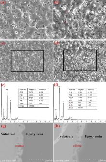
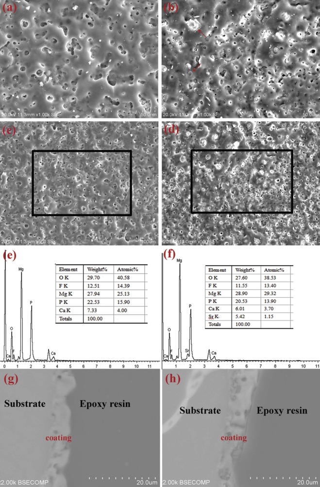
The surface morphologies of the MAO coatings prepared on the as-cast Mg-Sr alloys are shown in Fig. 1(a) and (b). It can be seen that there exist many micropores on the surface of the coatings, which is the typical feature of MAO coating. It is well known that the large discharge sparks and “ melt discharging channel” during the MAO process are inevitable to induce the micropores. Refined structure with tiny discharging micropores was observed on the outer surface of the Sr-CaP coating in comparison with that of the CaP coating. Some of the micropores are embedded with compound particles (marked by red arrows in Fig. 1(b)), while the other pores apparently exist in the Sr-CaP coating. This sealing phenomenon can be seen from the previous study[30]. The EDS results as shown in Fig. 1(e) and (f) demonstrate that oxygen (O), fluorine (F), magnesium (Mg), phosphorus (P) and calcium (Ca) exist in the CaP coating. Besides the above elements, 1.15 at.% strontium was found in the Sr-CaP coating. The cross-sectional morphology with the information of thickness is presented in Fig. 1(g) and (h). It can be seen that both of the coatings are well combined with the substrate and include an outer porous layer and an inner compact layer[31]. The thickness values of the CaP and Sr-CaP coatings are about 5 µ m and 7 µ m, respectively. The difference in thickness is caused by the different reaction intensities in the two electrolytes. The hydroxyl of the electrolyte containing Sr(OH)2 can enhance the conductivity of the electrolyte, which is also the reactant of the coating formation[32, 33].
Fig. 1. Surface morphology of the CaP (a) and Sr-CaP (b) coatings; low magnification images (c, d) and corresponding EDS spectra (e, f); the cross-sectional morphology of the CaP (g) and Sr-CaP coatings (h).
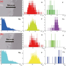
The cross-sectional elemental distributions of O, F, Mg, P and Ca in two coatings (Fig. 2) are similar. Oxygen and phosphorous homogeneously distribute in the coatings. Fluorine and magnesium mainly distribute in the inner side of the coatings and calcium distributes at the outer side. The distribution of Sr is hard to be detected due to its low content.
Fig. 2. Elemental distribution at a varying distance from substrate to the coating surface by EDS line scan of the CaP (a) and Sr-CaP (b) coatings.
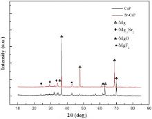
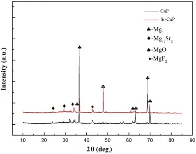
XRD patterns obtained from the two kinds of coatings are shown in Fig. 3. It can be seen that besides the peaks corresponding to Mg-Sr alloy substrate, only small peaks corresponding to MgO and MgF2 can be detected. No peaks corresponding to the Sr, Ca and P containing phases could be detected in the above two coatings, despite certain amounts of Sr, Ca and P were revealed in the EDS analysis. It can be seen that the Sr, Ca and P elements in the two coatings should be in the form of amorphous state, a similar observation as reported by Yao et al.[34]
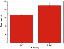
Fig. 4 shows the drop time of the as-cast Mg-Sr samples with MAO coatings prepared at the same parameters. The drop time of Sr-CaP coating is higher than that of CaP coating, indicating a better corrosion resistance.
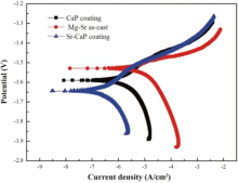
Potentiodynamic polarization was applied to evaluate the corrosion resistance of the Mg-Sr alloys with and without coating. Fig. 5 represents the polarization curves of different samples immersed in Hanks’ solution. The corrosion potential (Ecorr), the current density (Icorr), polarized resistant (Rp), and the corrosion rate (CR) calculated according to the ASTM-G102-89 standard[35] are listed in Table 1. The polarization curves indicate that both the anodic and cathodic reaction rates are much reduced for the CaP and Sr-CaP coatings in comparison with the Mg-Sr substrate, as evidenced by a large shift of the curve toward lower densities for similar potentials. The cathodic polarization curve of the Sr-CaP coating increases slowly compared with the CaP coating and Mg-Sr alloy. The order of cathodic current density can be ranked as an increasing series: Sr-CaP coating < CaP coating < Mg-Sr alloy, indicating that the hydrogen evolution reaction is inhibited by the coating. The corrosion current densities (Icorr) of both the CaP and Sr-CaP coatings are lower than that of Mg-Sr substrate, indicating that the MAO coating significantly improves the corrosion resistance of Mg-Sr as-cast alloy. Additionally, the Sr-CaP coating possesses better corrosion resistance than the CaP coating with more positive corrosion potential (Ecorr), lower Icorr and larger polarization resistance (RP).
Fig. 5. Potentiodynamic polarization curves of the coatings and Mg-Sr substrate.
Table 1.
Table 1.
Table 1. Fitting data obtained from the polarization curve
β a (mV/decade)
β c (mV/decade)
Ecorr (V)
Icorr (µ A/cm2)
Rp (Ω /cm2)
CR (mm/y)
Mg-Sr substrate
107.3
254.9
-1.53
12.90
2.55 × 10³
0.74
CaP coating
345.2
254.1
-1.59
6.45
0.98 × 10⁴
0.37
Sr-CaP coating
148.3
549.6
-1.64
0.488
1.04 × 10⁵
0.03
Table 1. Fitting data obtained from the polarization curve
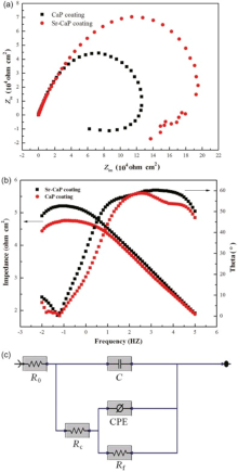
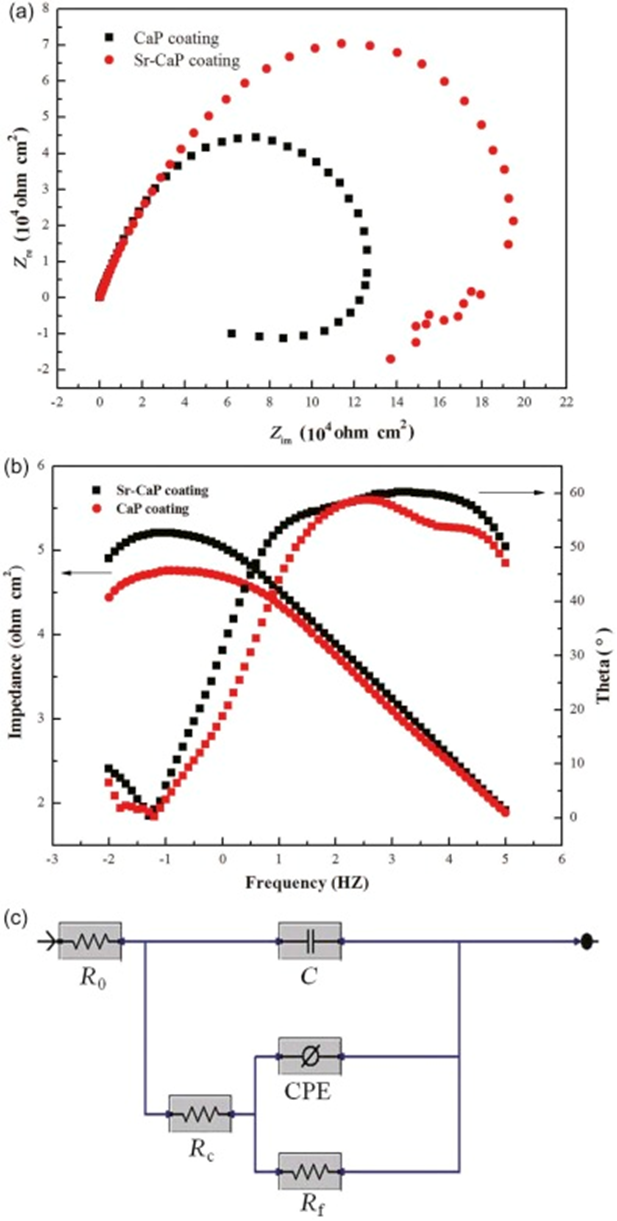
The electrochemical impedance spectroscopy (EIS) technique was applied to investigate the electrode/electrolyte interface and processes that occur on the coating surfaces. Fig. 6 shows the typical Nyquist and Bode plots of the spectra for the Sr-CaP and CaP coatings, respectively. Different EIS behaviors dependent on the chemistry of coating are observed. It can be seen that the Sr-CaP coating exhibits a larger dimension of capacitive loops in comparison with that of CaP coating, which means that it has a higher corrosion resistance.
Fig. 6. Nyquist (a), Bode plots (b) and Equivalent circuit (c) employed to fit the impedance data of the CaP and Sr-CaP coatings.
The recorded EIS spectrum shows similar features for Sr-CaP and CaP coatings. It is found that two time constants include one high-medium frequency capacitance loop and one low frequency capacitance loop. In the high-medium frequency region, a linear relationship can be observed between the absolute impedance and the frequency with a slope of -0.65 and phase angle approximately -60° . This frequency region corresponds to a purely capacitive behavior of the MAO coating/electrolyte interface. At the lowest frequency range, the phase angle is close to 0° , corresponding to a plateau in the impedance modulus vs frequency plot where the total resistance of the circuit can be obtained. The Sr-CaP coating shows the higher impedance value (Z curve) and the shift of the phase angle curve toward lower frequencies compared with the CaP coating. The influence on the degradation process of the coatings was analyzed based on the EIS results. The plots can be explained by the equivalent circuit as shown in Fig. 6. For the equivalent circuit, Rs is the solution resistance, Rc and Rf refer to the resistance of the outer porous layer and inner layer of MAO coating, respectively, C refers to a capacitor of the outer layer. The inner layer/interface capacity was described by a constant phase element (CPE), which was defined by two values, Y0 and n. If n is equal to 1, CPE is identical to a capacitor. Often a constant phase element is used in a model in place of a capacitor to compensate for the nonhomogeneity in the system[36, 37]. The data are fitted using the ZSimpwin 3.20 software and the errors are less than 10%. The fitted results are listed in Table 2. Both resistance of outer layer (Rc) and inner layer/interface (Rf) for Sr-CaP coating are significantly higher than those of the CaP coating. Additionally, the Rf of the coating is higher than the corresponding value of Rc by 3 orders of magnitude, indicating that the inner layer has main effect on the corrosion protection of the substrate. The similar observations also have been reported by Liang et al.[38]
Table 2.
Table 2.
Table 2. Results of the electrical parameters fitted from EIS data of Sr-CaP and CaP coatings
Sr-CaP coating
Ca-P coating
R0 (ohm)
45.15
43.99
C (F)
27.59 × 10⁻⁹
30.89 × 10⁻⁹
Rc (ohm)
378.1
294.2
Yo
1.373 × 10⁻⁶
1.608 × 10⁻⁶
N
0.68
0.71
Rf (ohm)
138.6 × 10³
48.15 × 10³
Table 2. Results of the electrical parameters fitted from EIS data of Sr-CaP and CaP coatings
3.3. Immersion tests
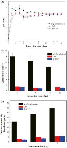
Immersion tests were undertaken to evaluate the long-term corrosion resistance of the coatings. It is well known that the overall corrosion reaction of magnesium in aqueous solution at its corrosion potential can be expressed as follows: Mg + 2H2O → Mg2+ + 2OH- + H2↑ . As a consequence, the degradation of Mg-Sr alloy leads to an increase of the pH value in the surrounding area. The pH value in the Hanks’ solution with samples immersed for 14 days is shown in Fig. 7(a). It can be seen that the pH value of the coatings is obviously lower than that of the Mg-Sr substrate at most of the time points. Furthermore, the pH value of the Sr-CaP coating is lower than those of the CaP coating at all time points. The Mg-Sr alloy sample reacts with H2O so that the pH value reaches approximately 11.9 after one day of immersion, then the pH value fluctuates in the first 3 days owing to the formation and dissolution of Mg(OH)2 on the surface. Then the pH value slightly decreases until the samples completely disappear after 11 days. The pH values of the Sr-CaP and CaP samples show similar changes at the initial and ascend gradually after 4 days, which is probably caused by the breaking of the coating. The pH value of CaP coating reaches about 11.1 later and remains stable for the rest of the days, whereas the Sr-CaP coating has certain advantages over other samples in the corrosion resistance.
Fig. 7. (a) pH variation of Mg-Sr substrate, CaP and Sr-CaP coating during immersion of 14 days, (b) corrosion rate calculated by mass loss after immersion for 3, 7, 14 days, (c) Mg ions release after immersion for 1, 3 and 5 days in Hank’s solution.
After addition of chromic acid solution, corrosion assessment by weight loss measurement after immersion for 3, 7 and 14 days was analyzed and illustrated graphically as corrosion rate (CR) in Fig. 7(b). It is apparent that the Mg-Sr alloy exhibits the fastest degradation rate at all time points among the three different samples, followed by that of CaP and Sr-CaP coatings. The CR of the Mg-Sr alloy is almost 5 times bigger than the coatings and is completely corroded after 11 days, indicating that both of the coatings display excellent protection effect in Hanks’ solution. Moreover, the Sr-CaP coating owns better protection effect compared with CaP coating.
Fig. 7(c) shows the change of Mg concentration after immersion for 1, 3 and 5 days to evaluate the ions released at the initial period. It can be seen that the Mg2+ concentration for three of them increases with the increase of immersion time. The order of Mg2+ concentration can be ranked as an increasing series: Sr-CaP coating < CaP coating < Mg-Sr alloy. The Mg2+ concentration of the coatings is significantly lower than that of Mg-Sr alloy, indicating that the initial rapid corrosion of the substrate is inhibited, which is also in accordance with the result of weight loss test.
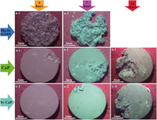
Fig. 8 shows the typical appearances of Mg-Sr alloy substrate, CaP and Sr-CaP coatings after immersion for 3, 7 and 14 days. It can be seen that the Mg-Sr alloy degrades severely with a deep-layered corrosion character on the surface after immersion for 3 days, and local corrosion takes place on the CaP coating sample. By contrast, the Sr-CaP sample almost keeps intact after the immersion for 3 days. The great mass of Mg-Sr alloy degrades after 7 days, and the local corrosion expands and evolves severely on the surface of CaP coating compared with some local corrosion originated from the margin of the Sr-CaP coating. The Mg-Sr alloy sample gets completely vanished after immersion for 11 days. The local parts of CaP and Sr-CaP coatings corrode more severely after 14 days. Thus, as can been seen, both of the MAO coatings can slow down the degradation rate of the Mg-Sr substrate. Moreover, the Sr-CaP coating has the lower corrosion rate and better corrosion resistance. Additionally, the corrosion product (marked by the red arrows) deposited in the Hanks’ solution can also be found on both of the surfaces.
Fig. 8. Surface morphology of different samples immersed in Hanks’ solution for 3, 7, 14 days: (a) Mg-Sr substrate, (b) CaP and (c) Sr-CaP coating.
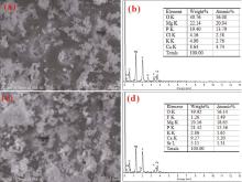
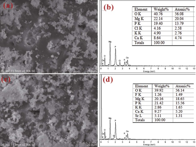
In vitro degradation and mineralization on the surfaces of CaP and Sr-CaP coatings were evaluated after 14 day’ immersion in Hanks’ solution. SEM images depicting the surface morphology are presented in Fig. 9. It can be seen that corrosion products with some cluster randomly scatter on the surface of coatings. For the CaP coating, there is marked difference in surface morphology after 14 days of immersion in comparison with that in Fig. 1(a) since a spot of particles deposit on the surface, as shown in Fig. 9(a). Comparatively, a number of particles are deposited on the Sr-CaP MAO coating as shown in Fig. 9(c). Fig. 9(b) and (d) shows the elemental compositions on the surfaces of CaP and Sr-CaP coatings after immersion, as analyzed by EDS. Elements such as Cl and K are found on the coatings, which come from the Hanks’ solution, while the contents of Ca and P are all maintained at higher levels due to the precipitations from the solution. The ability to form the apatite on the implant surface in simulated body fluid is considered as an indication of osteointegration capability[39]. The content of Ca and P in Sr-CaP coating is higher than that in CaP coating, indicating the better mineralization performance.
Fig. 9. Mineralization morphology and the EDS map scans of element composition of CaP sample (a, b) and Sr-CaP (c, d) sample after 14 day’ immersion in Hank’s solution.
3.4. Cytotoxicity
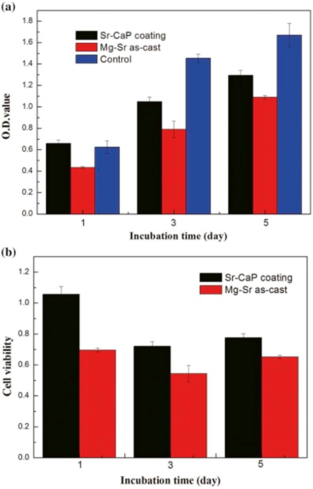
The indirect-cytotoxicity test is commonly applied to investigate the release of potential toxic particles of materials for medical applications in vitro. Fig. 10 shows the viability of MC3T3-E1 cells after incubation with extracts for 1, 3 and 5 days. Cell proliferation is evaluated by CCK8 assay at each time point and the results are shown as the optical density (O.D.) values and cell viabilities. It can be seen that after co-culture for 1 day, the O.D. value of Mg-Sr alloy is apparently lower than that of the control group, while the O.D. value of Sr-CaP coating is slightly higher than that of the control group. The O.D. value of all the groups increases with the incubation time, indicating the ascending trends of cell proliferation. However, O.D. value of the Mg-Sr alloy and Sr-CaP coating is lower than that of the control group after 3 and 5 days of culture, while the O.D. value of the Sr-CaP coating is still higher than that of the Mg-Sr alloy. According to the assessment of the grade of cytotoxicity in ISO 10993-5, the cell viability rate (CVR) of the Sr-CaP coating is 106%, indicating no cytotoxicity, while the Mg-Sr alloy shows low cytotoxicity with CVR of 70% on the first day. The viability rates of both Sr-CaP coating and Mg-Sr alloy decrease after incubation for 3 and 5 days due to the relatively slow cell growth compared with the control group. In short, the Sr-CaP coating demonstrates an enhanced cytocompatibility than the Mg-Sr alloy substrate, suggesting acceptable bio-safety for the medical implant applications.
Fig. 10. Optional density (a) and cell viability (b) of MC3T3 cells after incubation with extracts of three different samples for 1, 3 and 5 days.
3.5. Animal experiment
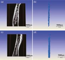
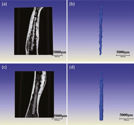
It was found that the in vitro degradation measurements including hydrogen evolution, mass loss and electrochemical behavior could not factually reflect the in vivo status [29]; thus, in vivo degradation after implantation is needed for non-destructive examination in 3D by XRT. The in vivo degradation morphology of the remaining magnesium alloy implants and also surrounding bone tyear in the rabbit distal femur is displayed in Fig. 11 by XRT in 3D reconstruction.
Fig. 11. 3D XRT topographies of rabbit femur with an intramedullary Mg-Sr alloy (a, b) and with Sr-CaP coating (c, d) implant scanned in vivo after implantation of 8 weeks.
It can be clearly observed that Mg-Sr alloy rod is destroyed by severe pitting after implantation for 8 weeks, and the volume of the rod is significantly decreased, while the MAO coated rod shows a slow and uniform corrosion with scattered areas of severe pitting. The rod with coating still maintains its integrity, except for the severe degradation in the proximal site. It is found that degradation of the implants differs in different regions, exhibiting faster corrosion in the distal (close to metaphyseal region) than bone marrow cavity of the diaphyseal region. The similar observation was also reported by Gu et al.[12]. The corrosion rate was calculated according to Eq. (2) in which the remaining implant volume was obtained from the XRT analysis which revealed that Mg-Sr alloy with the Sr-CaP coating (0.75 mm/y) degraded significantly slower in vivo than the Mg-Sr substrate (1.3 mm/y).
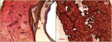
Fig. 12 shows the histology of cross-sections of the bone-implanted sample. Due to the rabbit femur with an intramedullary implantation, the implants show indirect contact with the surrounding bone tyear. However, during the degradation process of magnesium alloy, several degradation products are released[40] and may lead to negative effects on the tyear. It can be found that the bone around the Mg-Sr alloy with Sr-CaP coating exhibits normal histological morphology. Comparatively for the Mg-Sr alloy, obvious resorption lacunae are observed in the osseous tyear, which may be attributed to the rapid degradation. It is reported that corrosion occurring in degradable implants may stimulate inflammation, osteoclast activation, and osteoblast inhibition. This pathway induces osteolysis and may also trigger hypersensitivity and allergic reactions[41]. Therefore, the protection of Sr-CaP coating can effectively retard the degradation and enhance the tyear compatibility.
Fig. 12. Histological thin slides of Mg-Sr alloy (a) and Sr-CaP coating (b) implants at implantation of 8 weeks.
4. Discussion
A large number of recent studies have emphasized the possibilities of Mg alloys as a new class of degradable biomaterials for orthopedic applications. However, the key year that remains to be solved is the incompatible or unmatched degradation including in vivo resorption being too rapid, too localized, or unpredictable, the degradation of Mg with hydrogen gas evolution which may accumulate adjacent to the implant in the body [7], and over-dosage of potentially toxic alloying elements which populate the Mg alloy[42].
Surface modification is proved to be the most effective method to control corrosion of magnesium alloys and also improve the bioactivity. MAO technique can produce uniformly porous and firmly adherent oxide coatings on implant surfaces with excellent abrasion and corrosion resistance. Moreover, MAO allows forming coatings containing Ca(II) phosphates on the surface of titanium and magnesium[29, 34, 43]. Several studies showed that the incorporation of Ca and P in the MAO coatings could potentially enhance the bioactivity of the coatings[44, 45]. In vitro and in vivo studies have proven that strontium (Sr) can increase bone formation, reduce bone resorption and improve bone mechanical strength in humans [46]. In view of the fact that the coatings containing calcium phosphate with additives of strontium phosphate may be of interest for orthopedic applications, the Sr-CaP coating is fabricated in the Ca and Sr containing polyphosphate electrolyte via MAO on the Mg-Sr alloy.
In this case, the electrochemical oxidation of the magnesium alloy surface is carried out under the action of electric spark and arc breakdown in a growing oxide and electrolyte boundary. The latter allows introducing into the coating composition components of the electrolyte (i.e. Sr) in the form of their thermolysis products resistant to dissolution[47]. It is found that Ca, Sr and P elements are incorporated into the oxide coating, and a porous layer with 7 µ m thickness is formed on the magnesium surface. The atomic ratios of Ca and Sr in the coating are 3.70% and 1.15%, respectively, as confirmed by EDS.
Generally, the corrosion resistance of coatings is governed by original morphology/structure and thickness[48], the chemical stability of the main components in SBF[48, 49], and the apatite formation ability[48, 50]. In view of the results of the electrochemical and immersion tests, the Sr-CaP coatings can effectively control the degradation of the Mg-Sr alloy substrate. Compared with the CaP coating, the protective ability of the Sr-CaP coating is better. Considering the similarity of the phase composition between the two coatings, the better protective ability of the Sr-CaP coating may be attributed to the refine structure, larger thickness, sealing morphology and apatite formation ability.
It can be seen from Fig. 1 that the thickness of the Sr-CaP increases in comparison with CaP coating. It is deduced that the hydroxyl of the electrolyte containing Sr(OH)2 can enhance the conductivity of the electrolyte and is also the reactant of the coating formation. The morphology with micro-pores sealing of the Sr-CaP coating shows that it can also prevent the Mg-Sr alloy substrate from reacting with the SBF solution. It is found that the addition of Sr into electrolyte is beneficial for evenly charging during the processing of MAO coating, which produced a more refined structure with outer layer of homogeneous micro-pores and compact inner interface as reflected by the SEM observation and EIS analysis. Thus it is deduced that strontium can be incorporated into calcium phosphate, and the Sr-containing coatings thus formed could effectively protect the magnesium substrate from degradation. The long-term degradation behavior of the coatings via pH monitoring and weight loss measurement shows that the pH value of the Sr-CaP coating is significantly lower than those of substrate, and the in vitro degradation maintains at a slow corrosion rate of approximately 3 mm/y, also lower than that of the CaP coating. The results of Mg concentration in Fig. 7(c) also correspond with the pH variation and weight loss. In brief, the Sr-CaP coating possesses the excellent in vitro corrosion resistance. On the other hand, to evaluate the effectiveness of the Sr-CaP coating in vivo, intramedullary implantation in the rabbit femur was employed and examined in 3D by XRT. It is found that the degradation in vivo (0.75 mm/y) of the coating is about 4 times slower than that in vitro (3 mm/y). Sanchez et al. [51] reported that the possible corrosion rate in vivo is on average 1-5 times lower than the corrosion rate obtained in vitro, which is in accordance with our results. Moreover, the Sr-CaP coating could effectively retard the degradation of Mg-Sr substrate (1.3 mm/y), which is suitable for the orthopedic application.
Sr is a known osteopromotive element which can activate osteoblastic cell replication through the calcium sensing receptor (CaSR) and signal-regulated kinase (ERK) 1/2 phosphorylation, inhibit bone resorption by increasing osteoprotegerin (OPG) and decreasing receptor activator of nuclear factor kappa B ligand (RANKL) expression by osteoblasts[27, 52]. In the present study, the addition of Sr on the bioactivity of the MAO coating was evaluated by in vitro cell test. The results of cytotoxicity show that the Sr-CaP coating can meet the requirements of medical device according to ISO 10993. Additionally, the Sr-CaP coating promotes the proliferation of the osteoblast cells, which should be attributed to the existence of Sr and Mg. Prior studies of Sr containing coating also proved the effects of Sr incorporation that could impact downstream osteoclast cell behavior and improve the bone-implant integration [23].
5. Conclusion
Sr-CaP coating has been successfully fabricated on Mg-Sr alloy by MAO process. Results show that the addition of strontium changes the microstructure of the coating and also leads to an increase in the thickness of coating. The Sr-CaP coated Mg-Sr alloy possesses a better corrosion resistance in vitro and retards the degradation in vivo. On the other hand, the incorporation of Sr is an effective method to improve the biocompatibility/bioactivity of the MAO coating. It can, therefore, be concluded that the Sr-CaP coating has a significantly higher ability to promote the new bone formation, which is a good candidate coating for bone repair application.
AcknowledgementsAcknowledgments:
This work was financially supported by the National High Technology Research and Development Program of China (No. 2015AA033701), the Chinese Academy of Sciences-Croucher Founding Scheme for Joint Laboratories (Ref. CAS 14303) and Foundation of Jiangsu Collaborative Innovation Center of Biomedical Functional Materials.
The authors have declared that no competing interests exist.
H. Windhagen, K. Radtke, A. Weizbauer, J. Diekmann, Y. Noll, U. Kreimeyer, R. Schavan, C. Stukenborg-Colsman, H. Waizy, Biomed. Eng. Online12 (2013)62-71. [本文引用:1]
[11]
D. Sreekanth, N. Rameshbabu, K. Venkateswarlu, Ceram. Int. 38(2012) 4607-4615. [本文引用:1]
[12]
X. N. Gu, N. Li, W. R. Zhou, Y. F. Zheng, X. Zhao, Q. Z. Cai, L. Q. Ruan, Acta Biomater. 7(2011) 1880-1889. [本文引用:2]
[13]
K. C. Kung, T. M. Lee, T. S. Lui, J. Alloy. Compd. 508(2010) 384-390. [本文引用:1]
[14]
X. Lin, X. Wang, L. Tan, P. Wan, X. M. Yu, Q. Li, K. Yang, Ceram. Int. 40(2014)10043-10051. [本文引用:2]
[15]
J. P. Schreckenbach, G. Marx, F. Schlottig, M. Textor, N. D. Spencer, J. Mater. Sci. Mater. Med. 10(1999) 453-457. [本文引用:1]
[16]
D. Q. Wei, Y. Zhou, D. C. Jia, Y. M. Wang, Acta Biomater. 3(2007) 817-827. [本文引用:1]
[17]
J. Y. Reginster, E. Seeman, M. C. De Vernejoul, S. Adami, J. Compston, C. Phenekos, J. P. Devogelaer, M. D. Curiel, A. Sawicki, S. Goemaere, O. H. Sorensen, D. Felsenberg, P. J. Meunier, J. Clin. Endocrinol. Metab. 90(2005) 2816-2822. [本文引用:1]
[18]
C. Roux, Bone40 (2007) S9-S11. [本文引用:1]
[19]
S. Ortolani, S. Vai, Bone38 (2006) 19-22. [本文引用:2]
[20]
M. D. Grynpas, P. J. Marie, Bone11 (1990) 313-319. [本文引用:1]
[21]
Y. J. Lu, P. Wan, L. Tan, B. C. Zhang, K. Yang, J. X. Lin, Surf. Coat. Technol. 252(2014)79-86. [本文引用:1]
[22]
K. H. Nan, T. Wu, J. H. Chen, S. Jiang, Y. Huang, G. X. Pei, Mater. Sci. Eng. C29 (2009)1554-1558. [本文引用:1]
[23]
J. Yan, J. Sun, P. K. Chu, Y. Han, Y. M. Zhang, J. Biomed. Mater. Res. Part A101(2013)2465-2480. [本文引用:3]
[24]
C. Liu, P. Wan, L. Tan, K. H. Wang, K. Yang, J. Orthop. Transl. 2(2014) 139-148. [本文引用:2]
[25]
C. Capuccini, P. Torricelli, F. Sima, E. Boanini, C. Ristoscu, B. Bracci, G. Socol, M. Fini, I. N. Mihailescu, A. Bigi, Acta Biomater. 4(2008) 1885-1893. [本文引用:1]
[26]
X. Lin, L. Tan, Q. Zhang, K. Yang, Z. Q. Hu, J. H. Qiu, Acta Biomater. 9(2013)8631-8642. [本文引用:1]
[27]
X. N. Gu, X. H. Xie, N. Li, Y. F. Zheng, L. Qin, Acta Biomater. 8(2012) 2360-2414. [本文引用:2]
[28]
S. G. Wang, S. C. Wang, L. Zhang, Acta Metall. Sin. 49(2013) 897-910 (in Chinese). [本文引用:1]
[29]
F. Witte, J. Fischer, J. Nellesen, C. Vogt, J. Vogt, T. Donath, Acta Biomater. 6(2010)1792-1799. [本文引用:3]
[30]
J. Gan, L. Tan, K. Yang, Z. Q. Hu, Q. Zhang, X. M. Fan, Y. D. Li, W. R. Li, J. Mater. Sci. Mater. Med. 24(2013) 889-901. [本文引用:1]
[31]
P. Wan, X. Lin, L. Tan, L. Li, W. R. Li, K. Yang, Appl. Surf. Sci. 282(2013) 186-194. [本文引用:1]
[32]
Y. K. Pan, C. Z. Chen, D. G. Wang, X. Yu, J. Biomed. Mater. Res. Part B100 (2012)1574-1586. [本文引用:1]
[33]
C. L. Chu, X. Han, J. Bai, F. Xue, P. K. Chu, Surf. Coat. Technol. 213(2012) 307-312. [本文引用:1]
[34]
Z. P. Yao, L. Li, Z. H. Jiang, Appl. Surf. Sci. 255(2009) 6724-6728. [本文引用:2]
[35]
ASTM-G102-89, Annual Book of ASTM Stand ards, American Society forTesting and Materials, Philadelphia, PA, 1999. [本文引用:1]
[36]
G. Song, A. Atrens, D. StJohn, X. Wu, J. Nairn, Corros. Sci. 39(1997) 1981-2004. [本文引用:1]
[37]
Y. W. Song, D. Y. Shan, R. S. Chen, F. Zhang, E. H. Han, Mater. Sci. Eng. C29 (2009)1039-1045. [本文引用:1]
[38]
J. Liang, P. B. Srinivasan, C. Blawert, M. Störmer, W. Dietzel, Electrochim. Acta. 54(2009) 3842-3850. [本文引用:1]
[39]
Y. Shi, M. Qi, Y. Chen, P. Shi, Mater. Lett. 65(2011) 2201-2204. [本文引用:1]
[40]
D. Persaud-Sharma, A. McGoron, J. Biomim. Biomater. Tyear Eng. 12(2012)25-39. [本文引用:1]
[41]
N. Hallab, J. J. Jacobs, J. Black, Biomaterials21 (2000) 1301-1314. [本文引用:1]
[42]
N. T. Kirkland , J. Lespagnol, N. Birbilis, M. P. Staiger, Corros. Sci. 52(2010) 287-291. [本文引用:1]
[43]
O. P. Terleeva, Y. P. Sharkeev, A. I. Slonova, I. V. Mironov, E. V. Legostaeva, I. A. Khlusov, E. Matykina, P. Skeldon, G. E. Thompson, Surf. Coat. Technol. 205(2010)1723-1729. [本文引用:1]
[44]
Y. K. Pan, C. Z. Chen, D. G. Wang, Z. Q. Lin, Mater. Chem. Phys. 141(2013) 842-849. [本文引用:1]
[45]
H. Tang, F. P. Wang, Mater. Lett. 93(2013) 427-430. [本文引用:1]
[46]
Z. Y. Li, W. M. Lam, C. Yang, B. Xu, G. X. Ni, S. A. Abbah, K. M. C. Cheung, K. D. K. Luk, W. Lu, Biomaterials28 (2007) 1452-1460. [本文引用:1]
[47]
V. S. Rudnev, M. A. Medkov, T. P. Yarovaya, P. M. Nedozorov, Russ. J. Appl. Chem. 85(2012) 1856-1860. [本文引用:1]
[48]
Y. H. Gu, C. F. Chen, S. Band opadhyay, C. Y. Ning, Y. J. Zhang, Y. J. Guo, Appl. Surf. Sci. 258(2012) 6116-6126. [本文引用:3]
[49]
A. Seyfoori, S. Mirdamadi, A. Khavand i, Z. SeyedRaufi, Appl. Surf. Sci. 261(2012)92-100. [本文引用:1]
[50]
Y. H. Gu, S. Band opadhyay, C. F. Chen, C. Y. Ning, Y. J. Guo, Mater. Des. 46(2013)66-75. [本文引用:1]
[51]
A. H. M. Sanchez, B. J. C. Luthringer, F. Feyerabend, R. Willumeit, Acta Biomater. 13(2015) 16-31. [本文引用:1]
[52]
A. A. Gorustovich, T. Steimetz, R. L. Cabrini, J. M. PortoLópez, J. Biomed. Mater. Res. Part A92(2010) 232-237. [本文引用:1]
1
2010
0.0
0.0
... IntroductionIn recent years, magnesium-based biodegradable implants have attracted more attention in the fields of orthopedics[1,2] ...
1
2006
0.0
0.0
... IntroductionIn recent years, magnesium-based biodegradable implants have attracted more attention in the fields of orthopedics[1,2] ...
1
2013
0.0
0.0
... Magnesium and its alloys degrade relatively safely in the human body[3,4], which avoids the removal of implants after healing ...
1
2010
0.0
0.0
... Magnesium and its alloys degrade relatively safely in the human body[3,4], which avoids the removal of implants after healing ...
1
2001
0.0
0.0
... Magnesium has an essential role in human metabolism[5,6], stimulates the growth of bone cells and promotes bone tyear healing[7,8] ...
1
2003
0.0
0.0
... Magnesium has an essential role in human metabolism[5,6], stimulates the growth of bone cells and promotes bone tyear healing[7,8] ...
2
2005
0.0
0.0
... Magnesium has an essential role in human metabolism[5,6], stimulates the growth of bone cells and promotes bone tyear healing[7,8] ...
... However, the key year that remains to be solved is the incompatible or unmatched degradation including in vivo resorption being too rapid, too localized, or unpredictable, the degradation of Mg with hydrogen gas evolution which may accumulate adjacent to the implant in the body [7], and over-dosage of potentially toxic alloying elements which populate the Mg alloy[42] ...
3
2015
0.0
0.0
... Magnesium has an essential role in human metabolism[5,6], stimulates the growth of bone cells and promotes bone tyear healing[7,8] ...
... Previous studies indicated that the MAO coating could effectively control the degradation of magnesium matrix by in vitro and in vivo experiments[8,14] ...
... [8] fabricated a bioactive Ca-P containing MAO coating on pure magnesium in an electrolyte solution consisting of calcium hydroxide, sodium hexametaphosphate and potassium fluoride ...
1
2013
0.0
0.0
... In addition, the specific strength and the similarity of Young's modulus of biodegradable Mg alloys to that of natural bone[9] reduce the risk of stress shielding in orthopedic applications ...
1
2013
0.0
0.0
... However, the initial rapid degradation leads to the loss of mechanical integrity and hydrogen evolution, which can retard the bone growth by acting as a physical barrier[10] ...
1
2012
0.0
0.0
... Micro-arc oxidation (MAO) is a promising technology to produce porous and firmly adherent coatings on substrates[11] ...
2
2011
0.0
0.0
... It has been intensively investigated as a class of biomedical coatings on magnesium alloys in recent years due to the better corrosion resistance, abrasion resistance and bioactivity[12] ...
... [12] ...
1
2010
0.0
0.0
... The MAO technique can be used to control surface properties, such as oxide thickness, chemical composition, pore size, and roughness[13] ...
2
2014
0.0
0.0
... Previous studies indicated that the MAO coating could effectively control the degradation of magnesium matrix by in vitro and in vivo experiments[8,14] ...
... Moreover, the electrolyte solution containing bioactive elements, such as calcium, phosphate and silicon, has been developed to enhance the biological compatibility and activity of MAO coatings for magnesium and its alloys[14,15,16] ...
1
1999
0.0
0.0
... Moreover, the electrolyte solution containing bioactive elements, such as calcium, phosphate and silicon, has been developed to enhance the biological compatibility and activity of MAO coatings for magnesium and its alloys[14,15,16] ...
1
2007
0.0
0.0
... Moreover, the electrolyte solution containing bioactive elements, such as calcium, phosphate and silicon, has been developed to enhance the biological compatibility and activity of MAO coatings for magnesium and its alloys[14,15,16] ...
1
2005
0.0
0.0
... Strontium (Sr) has been recently reported for its use in medical applications[17,18,19] ...
1
2007
0.0
0.0
... Strontium (Sr) has been recently reported for its use in medical applications[17,18,19] ...
2
2006
0.0
0.0
... Strontium (Sr) has been recently reported for its use in medical applications[17,18,19] ...
... There are a growing number of evidence that Sr influences bone remodeling by affecting both bone resorption and bone formation[19] ...
1
1990
0.0
0.0
... Sr is a natural bone-seeking trace element that accumulates in the skeleton[20] ...
1
2014
0.0
0.0
... Recently, some novel biomaterials such as strontium-substituted calcium phosphates and a series of Sr containing magnesium alloys have been developed to improve the biocompatibility of the implants[21,22,23] ...
1
2009
0.0
0.0
... Recently, some novel biomaterials such as strontium-substituted calcium phosphates and a series of Sr containing magnesium alloys have been developed to improve the biocompatibility of the implants[21,22,23] ...
3
2013
0.0
0.0
... Recently, some novel biomaterials such as strontium-substituted calcium phosphates and a series of Sr containing magnesium alloys have been developed to improve the biocompatibility of the implants[21,22,23] ...
... Several studies have shown that strontium containing hydroxyapatite (Sr-HA) is a bioactive bone cement that promotes osteoblast attachment and mineralization in vitro and bone growth and osteointegration in vivo[23] ...
... Prior studies of Sr containing coating also proved the effects of Sr incorporation that could impact downstream osteoclast cell behavior and improve the bone-implant integration [23] ...
2
2014
0.0
0.0
... [24] designed the Mg-Sr alloys as bone graft substitutes and proved that Mg-1 ...
... 5 wt% Sr alloy was studied in our previous work[24] ...
1
2008
0.0
0.0
... [25] employed pulsed-laser deposition to prepare Sr-HA coating on titanium substrates ...
1
2013
0.0
0.0
... The work voltage, work frequency, work duty cycle and preparation time were 360 V, 1000 Hz, 40% and 5 min, respectively, as was followed in our previous study[26] ...
2
2012
0.0
0.0
... 6 mm) were implanted into predrilled bone tunnels in the femur along the axis of the shaft from the distal femur using established surgical and model protocols[27] ...
... Sr is a known osteopromotive element which can activate osteoblastic cell replication through the calcium sensing receptor (CaSR) and signal-regulated kinase (ERK) 1/2 phosphorylation, inhibit bone resorption by increasing osteoprotegerin (OPG) and decreasing receptor activator of nuclear factor kappa B ligand (RANKL) expression by osteoblasts[27,52] ...
1
2013
0.0
0.0
... The three dimensional structure was reconstructed and visualized[28], with an optimized threshold used to isolate the bone and materials from the background ...
3
2010
0.0
0.0
... (2)[29]: ...
... Animal experimentIt was found that the in vitro degradation measurements including hydrogen evolution, mass loss and electrochemical behavior could not factually reflect the in vivo status [29] ...
... Moreover, MAO allows forming coatings containing Ca(II) phosphates on the surface of titanium and magnesium[29,34,43] ...
1
2013
0.0
0.0
... This sealing phenomenon can be seen from the previous study[30] ...
1
2013
0.0
0.0
... It can be seen that both of the coatings are well combined with the substrate and include an outer porous layer and an inner compact layer[31] ...
1
2012
0.0
0.0
... The hydroxyl of the electrolyte containing Sr(OH)2 can enhance the conductivity of the electrolyte, which is also the reactant of the coating formation[32,33] ...
1
2012
0.0
0.0
... The hydroxyl of the electrolyte containing Sr(OH)2 can enhance the conductivity of the electrolyte, which is also the reactant of the coating formation[32,33] ...
2
2009
0.0
0.0
... [34] ...
... Moreover, MAO allows forming coatings containing Ca(II) phosphates on the surface of titanium and magnesium[29,34,43] ...
1
1999
0.0
0.0
... The corrosion potential (Ecorr), the current density (Icorr), polarized resistant (Rp), and the corrosion rate (CR) calculated according to the ASTM-G102-89 standard[35] are listed in Table 1 ...
1
1997
0.0
0.0
... Often a constant phase element is used in a model in place of a capacitor to compensate for the nonhomogeneity in the system[36,37] ...
1
2009
0.0
0.0
... Often a constant phase element is used in a model in place of a capacitor to compensate for the nonhomogeneity in the system[36,37] ...
1
2009
0.0
0.0
... [38] ...
1
2011
0.0
0.0
... The ability to form the apatite on the implant surface in simulated body fluid is considered as an indication of osteointegration capability[39] ...
1
2012
0.0
0.0
... However, during the degradation process of magnesium alloy, several degradation products are released[40] and may lead to negative effects on the tyear ...
1
2000
0.0
0.0
... This pathway induces osteolysis and may also trigger hypersensitivity and allergic reactions[41] ...
1
2010
0.0
0.0
... However, the key year that remains to be solved is the incompatible or unmatched degradation including in vivo resorption being too rapid, too localized, or unpredictable, the degradation of Mg with hydrogen gas evolution which may accumulate adjacent to the implant in the body [7], and over-dosage of potentially toxic alloying elements which populate the Mg alloy[42] ...
1
2010
0.0
0.0
... Moreover, MAO allows forming coatings containing Ca(II) phosphates on the surface of titanium and magnesium[29,34,43] ...
1
2013
0.0
0.0
... Several studies showed that the incorporation of Ca and P in the MAO coatings could potentially enhance the bioactivity of the coatings[44,45] ...
1
2013
0.0
0.0
... Several studies showed that the incorporation of Ca and P in the MAO coatings could potentially enhance the bioactivity of the coatings[44,45] ...
1
2007
0.0
0.0
... In vitro and in vivo studies have proven that strontium (Sr) can increase bone formation, reduce bone resorption and improve bone mechanical strength in humans [46] ...
1
2012
0.0
0.0
... Sr) in the form of their thermolysis products resistant to dissolution[47] ...
3
2012
0.0
0.0
... Generally, the corrosion resistance of coatings is governed by original morphology/structure and thickness[48], the chemical stability of the main components in SBF[48,49], and the apatite formation ability[48,50] ...
... Generally, the corrosion resistance of coatings is governed by original morphology/structure and thickness[48], the chemical stability of the main components in SBF[48,49], and the apatite formation ability[48,50] ...
... Generally, the corrosion resistance of coatings is governed by original morphology/structure and thickness[48], the chemical stability of the main components in SBF[48,49], and the apatite formation ability[48,50] ...
1
2012
0.0
0.0
... Generally, the corrosion resistance of coatings is governed by original morphology/structure and thickness[48], the chemical stability of the main components in SBF[48,49], and the apatite formation ability[48,50] ...
1
2013
0.0
0.0
... Generally, the corrosion resistance of coatings is governed by original morphology/structure and thickness[48], the chemical stability of the main components in SBF[48,49], and the apatite formation ability[48,50] ...
1
2015
0.0
0.0
... [51] reported that the possible corrosion rate in vivo is on average 1-5 times lower than the corrosion rate obtained in vitro, which is in accordance with our results ...
1
2010
0.0
0.0
... Sr is a known osteopromotive element which can activate osteoblastic cell replication through the calcium sensing receptor (CaSR) and signal-regulated kinase (ERK) 1/2 phosphorylation, inhibit bone resorption by increasing osteoprotegerin (OPG) and decreasing receptor activator of nuclear factor kappa B ligand (RANKL) expression by osteoblasts[27,52] ...
Fabrication and Evaluation of a Bioactive Sr-Ca-P Contained Micro-Arc Oxidation Coating on Magnesium Strontium Alloy for Bone Repair Application


 , Yu Sun