


Polyethylene Oxide-Coated Electrospun Polyimide Fibrous Seperator for High-Performance Lithium-Ion Battery
[Xingxing Liang1, 2 , Ying Yang1, 3  , Xin Jin
4 , Jie Cheng5 ]
, Xin Jin|
|


A polyethylene oxide (PEO)-coated polyimide (PI) membrane was prepared by electrospinning method followed by a dip-coating and drying process for high-performance lithium-ion batteries (LIB). Semicrystal PEO was covered on the surface of the fibers and partially enmeshed in PI matrix, which formed unique porous structures. The pores with an average size of 4.1 µm and a porosity of 90% served as ion transport channels. Compared with the cell with Celgard 2400 membrane, the half-cell using PEO-coated PI membrane as a separator exhibits excellent electrochemical performance both at room temperature and at low temperature. The electrolyte uptaking rate of PEO-coated PI membrane was 170% and the ionic conductivity was 3.83 × 10⁻³ S cm-1. PEO-coated PI membrane possessed 5.3 V electrochemical window. The electrode-electrolyte interfacial resistance was 62.4 Ω. The capacity retention ratios with PEO-coated PI membrane were 86.4% at 5 C and 73.5% at 10 C at 25 °C and 75% at 5 C at 0 °C. Furthermore, the cell using the separator demonstrates excellent capacity retention over cycling. These advanced characteristics would boost the application of the PEO-coated PI membrane for high-power lithium ion battery.
The separator's performances exert an important impact on the lithium-ion battery (LIB) charge and discharge performance, especially under high power and low temperature conditions[1, 2, 3, 4, 5, 6, 7, 8]. However, there are some shortcomings with commercial polyethylene (PE) separators under large current and low temperature working conditions, such as relatively low porosity, poor wettability and poor thermal stability[2, 3, 4, 5]. Researchers have proved that electrospinning is one of efficient ways to modify the commercial separators or develop a self-standing membrane as a separator[9, 10]. One order of magnitude larger pore diameter is allowed since the tortuous pores formed in the electrospun membranes instead of straight pores in the commercial separators. Furthermore, such kind of structure with large porosity (~70%-90%) could improve the electrolyte uptaking and holding capacity (~200%-300%), which could further improve electrical properties under large current conditions[1, 11, 12, 13].
Electrospun polyacrylonitrile, polyvinylidene fluoride, poly (ethylene terephthalate), and poly (p-phenylene terephthalamide) membranes have been explored as a separator for potential application in lithium ion battery[14, 15, 16, 17, 18, 19, 20]. At temperatures above 80-100 ° C, such polymers may shrink, causing internal short-circuits. Therefore, polyimide (PI) with ultralow dielectric constant and high glass transition temperature have been adopted to prepare the highly porous nonwoven membranes recently. As reported, the electrode-electrolyte interfacial resistance of electrospun membrane was smaller (~100-120 Ω ) than that of commercial membranes (~160-200 Ω ) [21, 22, 23]. The ionic conductivity of liquid electrolyte-soaked electrospun membrane was in the range of 1.7-7.8 × 10⁻³ S cm-1[24]. Most of the electrospun membranes were tested at room temperature (~25 ° C); therefore, the performance of electrospun membranes at low temperature is still unknown.
The ionic conductivity of separator has to be further improved for better performances at larger power density and low temperature in practical use. Among various functional polymers, polyethylene oxide (PEO) can form a stable complex with the lithium salt without any organic plasticizer, which can help improve the ionic conductivity[25, 26]. Recent researches mainly focused on gel polymer electrolytes polymeric frameworks with PEO chains[27]. Yet other polymer chains, essential for reducing the crystallinity of PEO that retards ion motion in the polymeric framework, have rarely been studied. And the conductivity and durability of semi-crystallized PEO in liquid electrolyte as a physical dip-coating on a large surface area of porous material has rarely been reported.
Herein, we reported the preparation and properties of PEO dip-coated electrospun PI membrane as a separator under large current charge and discharge conditions at 0 and 25 ° C. Celgard 2400 microporous polyolefin membrane was used for comparison. The ionic conductivity was improved dramatically as the polar solvents can be strongly coordinated within the polymer chains due to the electron donor and acceptor groups of PI and PEO, and the high uptake percentage of the electrolyte was achieved in the large porous bulk. The thermal and electrochemical properties of the PEO dip-coated electrospun PI membrane determined it to be a good candidate separator to achieve large capacity, high-rate capability and long cycle life. Furthermore, PEO-coated PI electrospun membrane exhibited excellent performance with adequate durability at low temperature.
3, 3′ , 4, 4′ -biphenyl tetracarboxylic dianhydride (BPDA, > 99.5%, Changzhou Sun Chem Chemical Co., Ltd.), p-phenylenediamine (PPD, > 99%, Wuxi Changan Fine Chemical Factory), N, N-dimethylformamide (DMF, > 99.5%, West Long Chemical Co., Ltd.), Polyethylene oxide (PEO, Mw
All polyamic acid (PAA) spinning solutions were prepared in DMF, and polymerization was done according to literature[28]. The PAA electrospinning solution was 10 wt%. Electrospinning was carried out at the supply rate of 0.3 mL h-1, 15-25 kV on the spinneret, with 30 cm distance between the spinneret and the collector. The electrospun PAA fibrous membrane with 40 µ m thicknesses were collected within 2 h. The imidization from PAA to PI nanofibers was carried out as follows: heated up to 250 ° C within 30 min and held for 30 min; second, heated up to 370 ° C at a rate of 1 ° C per min and held for 30 min; and then cooled down to room temperature. The PI membrane was immersed in 2% PEO solution for 2 min followed by hanging and airing. The mass ratio of PI and PEO was about 1:1 by comparing mass before and after immersion. PI and PI/PEO membrane were dried under vacuum of 55 ° C for 5 h before use.
Fourier transform infrared (FTIR Nicolet 6700) spectra were obtained in the range of 4000-400 cm-1. The surface morphology and fiber diameters of the samples were investigated using a scanning electron microscope (SEM, LEO 1530). The thermostability of the samples was measured with differential scanning calorimetry (DSC, Q 2000) at a heating rate of 10 ° C min-1 under N2 flow. Thermogravimetry (TGA Q 5000) was performed under N2 flow at a heating rate of 10 ° C min-1. And crystallinity was examined with X-ray diffractometer (XRD, D/MAX-RM 2000, Rigaku) at a rate of 5° per min.
The wettability of the membrane in non-aqueous electrolyte was evaluated by contact angle measurements. Liquid electrolyte uptakes of the PEO-coated PI membrane were measured in 1 mol L-1 LiPF6 (EC: DMC: EMC = 1:1:1) solution at room temperature inside the glove box for 6 h. Liquid electrolyte-soaked membranes were weighed immediately after removing the excrescent surface electrolyte by wipes. The liquid electrolyte uptakes were calculated as follows:
Electrolyte uptakes (%)=(M1-M0)/M0∗100%
Herein, M0 and M1 were the weight of the membrane before and after immersion in the liquid electrolyte.
The porosity and pore size distribution of membranes were determined by using a mercury porosimeter (AutoPore IV 9500).
The ionic conductivities of different separators were measured by electrochemical impedance spectroscopy (EIS) using an electrochemical workstation (CHI 600, Shanghai Chen Hua Instrument Company). All the membranes were sandwiched as stainless steel | separator | stainless steel in a coin-type cell for ionic conductivity measurement. The impedance measurements were performed at amplitude of 10 mV over a frequency range of 1 Hz to 100 kHz at room temperature, and the ionic conductivity was calculated using the following equation:
σ =d/RbSσ =d/RbS
where, σ is the ionic conductivity, Rb is the bulk resistance measured with impedance spectra, and d and S are the thickness and area of the specimen, respectively.
The tested membranes were sandwiched as stainless steel | separator | Li in a coin-type cell for electrochemical window evaluation by a linear sweep voltammetry test at a scan rate of 10 mV s-1 from 2.5 V to 6.0 V. The interfacial resistance was determined by AC impedance spectrum with a Li | separator | Li cell over a frequency range of 65000 Hz to 0.01 Hz, with amplitude of 10 mV at 0 and 25 ° C, respectively.
A coin-type cell (CR 2032) was used in half-cell configuration assembled in a configuration of LiFePO4 | separator | Li to investigate the rate capability of the cell with various membranes. The cell for capacity tests was cycled at charge/discharge current rates of 0.2, 0.5, 1, 2, 5 and 10 C in a voltage range between 2.0 and 4.0 V at 0 and 25 ° C, respectively. The cell for cycling performance tests was cycled at a charge/discharge current rate of 5 C/5 C in a voltage range between 2.0 and 4.0 V at room temperature.
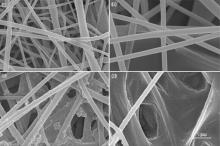
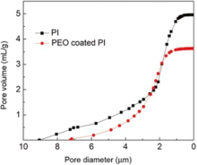
The morphology of electrospun PI and PEO-coated PI nanofibers were investigated by SEM. The electrospun PAA fibers with smooth surface were randomly distributed on the collector with diameter around 300 nm as shown in Fig. 1 (a). The diameters of PAA fibers did not change dramatically after thermal imidization, as shown in Fig. 1 (b). Fig. 1 (c) shows that the interconnected open pore structures still remained after being coated by PEO. A second level roughness formed due to PEO coating. As shown in Fig. 1 (d), the porous structure of PEO-coated PI composite membrane was still kept after the rate capability test. However, the PEO coating became smoother than the fresh PEO coating. This was related to the crystallinity of PEO. The pore diameter distributions were shown in Fig. 2. After being coated by PEO, the porosity slightly decreased from 96% to 90%, which indicated that the pores were kept in the membrane. The PI membrane pore diameter was 4.9 ± 4.2 µ m while the PEO-coated PI membrane pore diameter was 4.1 ± 3.1 µ m.
 | Fig. 1. Typical SEM images of (a) PAA nanofiber, (b) PI nanofiber, (c) PEO coated PI composite membrane, (d) PEO coated PI composite membrane of after 60 times charge and discharge cycle in current rate of 10 C. |
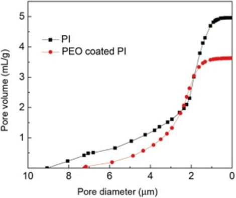 | Fig. 2. Pore diameter distribution of PI and PEO coated PI membrane. |
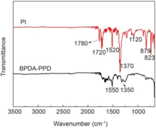
Imidization of PAA was confirmed by FTIR as shown in Fig. 3. After curing reaction at 370 ° C, the broad absorption band between 3500 and 2000 cm-1 dropped drastically, meanwhile the sharp absorption peaks at 1550 and 1360 cm-1, ascribed to the stretching vibration absorption of N-H, and O-H and CO-NH disappeared. The absorption peaks at 1780 cm-1 and 1720 cm-1 appearing in PI samples were related to the stretching vibration absorption of C = O in the imide structure, indicating that he PAA nonwoven was effectively converted into the corresponding PI nonwoven by thermal imidization.
 | Fig. 3. FTIR spectra of pristine BPDA-PPD and PI nanofiber. |
The thermal stability of the membrane was evaluated by DSC and TGA as shown in Fig. 4. PI membrane did not show any obvious melting peak below 370 ° C in Fig. 4 (a), which was much higher than the melting peak at 167 ° C of Celgard 2400 membrane as reported[6]. This significantly suppressed thermal shrinkage of PI membrane. The onset temperature of degradation of PI was over 550 ° C based on the TGA test in Fig. 4(b), which further demonstrated that the PI membrane either worked as a separator directly or as a separator scaffold for further modification. PI-based membrane didn't show any color change and shrinkage in the hot oven tests at 350 ° C.
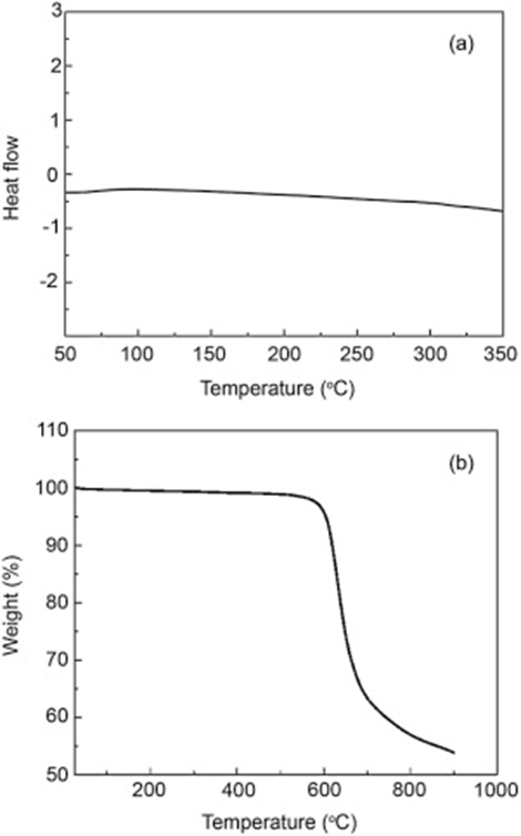 | Fig. 4. DSC (a) and TG (b) curves of PI fibrous membrane. |
As reported, amorphous PEO could be more efficient as solid electrolyte[29]. Electrospun amorphous PEO fibers were used as coating for comparison. Once the electrolyte was dropped onto the membrane, the electrospun amorphous PEO membrane was dissolved into the electrolyte, which destabilized the performance of PEO as coating on the LIB separator. The semi-crystalline phase PEO could be more stable in electrolyte. Fig. 5 shows the XRD patterns before and after charge/discharge tests. The XRD patterns of electrospun PI fiber exhibited two broad diffraction peaks around 18° and 23° in Fig. 5(a). It was recognized that electrospun PI fibers had only noncrystalline structure. The peaks corresponding to PEO at 15° , 18° and 23.2° displayed apparently as shown in the XRD patterns in Fig. 5(b), which indicated that PEO coating was in a typical semi-crystalline phase. As shown in Fig. 5 (c), only the peak corresponding to PEO at around 15° remained while others disappeared after cycling performance tests, which suggested that the semicrystalline structure could be partially transferred to noncrystalline structure during the charge/discharge process. Fig. 5 (d) demonstrates crystallinity of PEO after immersing the composite membrane in electrolyte directly for 7 days. It was found that the diffraction peaks were different from those in Fig. 5 (c), which indicated that the crystallinity transformation was not only related to the electrolyte dissolution but also to the charge/discharge process. As shown in Fig. 1(d), PEO in half crystalline phase could be stable in the electrolyte.
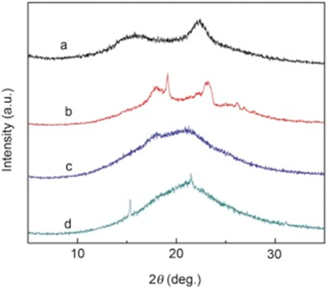 | Fig. 5. Wide-angle X-ray diffraction patterns of the polyimides. (a) PI, (b) PEO-coated PI membrane, (c) PEO coated PI membrane after 60 cycles and (d) PEO-coated PI membrane after immersion in electrolyte for 7 days. |
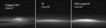
In comparison with the Celgrade 2400 membrane, PI and PEO-coated PI membrane showed better wettability for the electrolyte, as shown in Fig. 6, which can be attributed to low crystallinity of the electrospun membrane and the closer polarity between the polymer membrane and the liquid electrolyte. The thickness, liquid electrolyte uptakes and porosity of Celgard 2400, PI and PEO-coated PI membranes were listed in Table 1, respectively. The higher polarity and porosity of the PI and PEO-coated PI membrane guaranteed the penetration and high uptake percentage of the electrolyte. The high electrolyte uptakes proved that the relatively higher polarity and porosity of the membrane were conducive to the absorption of the electrolyte, leading to a higher ionic conductivity. Although electrolyte uptake rate of PEO-coated PI membrane (170%) was lower than that of PI membrane (340 %), it was yet far higher than that of Celgard membrane (40%).
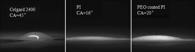 | Fig. 6. Contact angle (CA) images with liquid electrolyte droplet among the Celgard 2400, pure PI and PEO coated PI membrane composite membrane. |
| Table 1. Membrane parameters of Celgard 2400, PI and PEO-coated PI membrane |
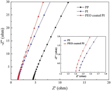
The ionic conductivity was obtained from the z′ axis of high-frequency intercept of Nyquist plots in Fig. 7. The inset is the same plot in Fig. 7, except that the z′ axis range is now restricted to [1.2, 1.8Ω ]. The PEO-coated PI membrane had the highest ionic conductivity of 3.83 × 10⁻³ S cm-1 after being soaked in liquid electrolyte, which was higher than that of 1.87 × 10⁻³ and 2.90 × 10⁻⁴ S cm-1 of liquid electrolyte-soaked PI and Celgard 2400 separator. Therefore, the ionic conductivities of PEO-coated PI membrane soaked in liquid electrolyte can better meet the conductivity requirement of lithium-ion battery, which was attributed to the fibrous fully interconnected pore structure and their high electrolyte uptake. And the relatively high ionic conductivity of PEO-coated PI electrospun membrane with lower electrolyte uptake can be attributed to the high PEO ionic conductivity.
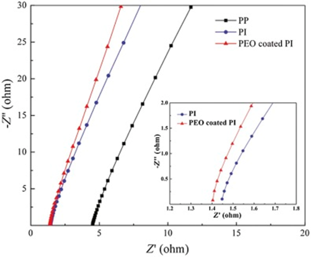 | Fig. 7. Ionic conductivities of liquid electrolyte-soaked Celgard 2400, PI and PEO-coated PI membrane. The inset is the same plot in Fig. 7, except that the z′ axis range is now restricted to [1.2, 1.8Ω ]. |
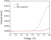
Fig. 8 shows the linear sweep voltammetry curves obtained from the cell (stainless steel | separator | Li) with PI and PEO-coated PI membrane, respectively. PEO-coated PI membrane and PI membrane possessed 5.3 V and 4.7 V electrochemical window while the Celgard 2400 membrane possessed a decomposition voltage around 4.5 V[30]. The results indicated that the highest electrochemical stability was obtained from PEO-coated PI membrane. Such kind of membrane could endow its potential compatibility with most high voltage materials used for lithium ion batteries.
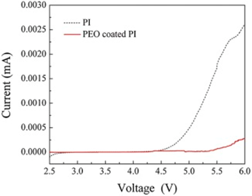 | Fig. 8. Linear sweep voltammetry curves of the cell (stainless steel | separator | Li) with PI and PEO-coated PI membrane as separator, respectively. |
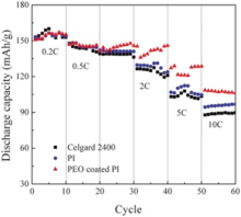
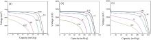
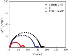
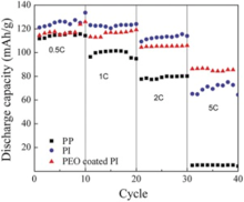
Fig. 9 shows the rate capabilities of the cells using the Celgard 2400, PI and PEO-coated PI membranes at 25 ° C. It was known clearly that both the cells with Celgard 2400 and PI membranes showed the same capacity of about 147 mAh g-1 at 0.5 C, the capacity retention ratio was about 93.9% and 96.6% at 1 C, 85.7% and 87.8% at 2 C, and then decreased rapidly to 70.1% and 72.8% at 5 C, 59.9% and 63.9% at 10 C, respectively. In contrast, the cell using PEO-coated PI membranes exhibited the initial capacity of about 147 mAh g-1 at 0.2 C. Then the capacity retention ratio kept 98.0% at 1 C and 92.5% at 2 C, 86.4% at 5 C and 73.5% at 10 C, respectively. The cell assembled with PEO-coated PI membrane possessed better rate capability than that of the Celgard 2400 and PI membrane. Both larger liquid electrolytes up-taking and holding capabilities and larger pores in PI based membrane led to high ionic conductivities and increased charge and discharge capacities in high current rate. PEO in the coating layer could increase the conductivity further as shown in Fig. 7. This should be the main reason for the best retention performance with PEO-coated PI membrane as a LIB separator. Fig. 10 depicts the discharge curves of cells assembled with Celgard 2400, PI and PEO-coated PI membrane as separators, wherein the cells were discharged in a voltage range between 2.0 and 4.0 V at various current densities ranging from 0.5 to 10 C. The discharge capacities of the cells gradually decreased with an increase of the discharge current density. Obviously, the PEO-coated PI membrane (Fig. 10(a)) presents higher discharge capacities than the PI membrane (Fig. 10(b)) and the Celgard 2400 (Fig. 10(c)) over a wide range of discharge current densities. The PEO-coated PI membrane possessed high porosities, small-bore, large specific surface areas and interconnected porous structures, and then, uptake large amounts of liquid electrolytes and offer effective conduction channels, which in turn lead to high ionic conductivities and increased discharge capacities. To further clarify the differences in rate capability, electrochemical impedance spectra (EIS) was carried out to identify the electrode kinetics of membranes. Nyquist plots of the cells are shown in Fig. 11. The semicircle at high frequency zone represented the charge-transfer resistance accompanied with migration of lithium ion between the electrode and electrolyte interface, and the straight slopping line corresponded to the diffusion of lithium ion in the active electrode. The order of the electrode-electrolyte interfacial resistance was: PEO-coated PI membrane (62.4 Ω ) < PI membrane (140.6 Ω ) < Celgard 2400 membrane (172.6 Ω ). Both the PEO-coated PI and PI electrospun membrane showed lower interfacial resistances than the commercial Celgard 2400 membrane, which was due to their large porosities and high electrolyte uptakes, as well as better membrane-electrode affinity.
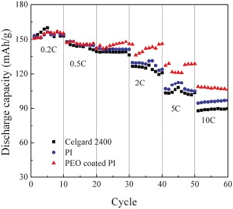 | Fig. 9. High rate capabilities of Li | separator | LiFePO4 cells with separators based on Celgard 2400, PI and PEO coated PI membrane (25 ° C, 2-4 V). |
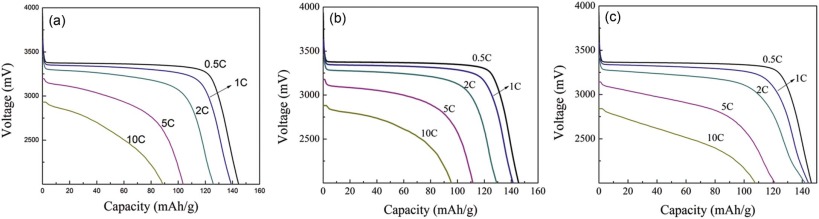 | Fig. 10. Discharge curves of Li | separator | LiFePO4 cells with separators based on (a) Celgard 2400, (b) PI and (c) PEO-coated PI membrane (25 ° C, 0.5 C-10 C, 2-4 V). |
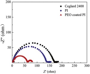 | Fig. 11. Impedance spectra of cell Li | separator | Li with Celgard 2400, PI and PEO-coated PI membrane as separators at 25 ° C, respectively. |
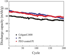
The cycle life was also an important parameter for rating lithium ion battery. Cycle performances of the cells using Celgard 2400, PI and PEO-coated PI membranes are depicted in Fig. 12 at a charge/discharge rate of 5 C/5 C as a function of cycle number (up to 200 cycles) at 25 ° C. A notable finding was that the PEO-coated PI membrane (85.1%) presented higher capacity retention than the PI membrane (77.2%) and the Celgard 2400 (83.9%) at a large discharge current density. It implied that the cell using PEO-coated PI membranes possessed good cycling performance. The remarkable improvement in the cycle performance of PEO-coated PI membranes was probably due to the favorable interfacial characteristics as well as strong affinity of PEO-coated PI membranes and the liquid electrolyte, as these factors could impart more facile ion transport and better electrolyte retention in the cell.
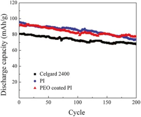 | Fig. 12. Cycle performance of Li | separator | LiFePO4 cells with separators based on Celgard 2400, PI and PEO coated PI membrane, respectively (25 ° C, 5 C, 2-4 V). |
Fig. 13 compares the rate capabilities of the cells using the Celgard 2400, PI and PEO-coated PI membranes at 0 ° C, respectively. The capacity retention ratios were 3.8%, 53.3%, 75% after ten cycles at 0.5, 1, 2 and 5 C for those cells using Celgard 2400, PI and PEO-coated PI membrane, respectively. The results indicated that PEO-coated PI membranes showed excellent rate capabilities at low temperatures. Superior rate performance was ascribed to the efficient ionic conduction of PEO coating since the glass transition temperature of PEO was around -60 ° C. The fast lithium ion transport could happen on the interface between electrodes and electrolyte in the cell. The interfacial impedance of the cell using Ceglard 2400, PI and PEO-coated PI membranes as separators at 0 ° C were presented in Fig. 14. The electrode-electrolyte interfacial resistances were 638 Ω , 348 Ω and 170 Ω for the Ceglard 2400, PI and PEO-coated PI membranes, respectively. The cell with PEO-coated PI membrane possessed the lowest interfacial resistance at low temperatures, which could yield the best rate capability.
 | Fig. 13. High rate capacities of the Li | separator | LiFePO4 cells using Celgard 2400, PI and PEO-coated PI membrane (0 ° C, 2-4 V). |
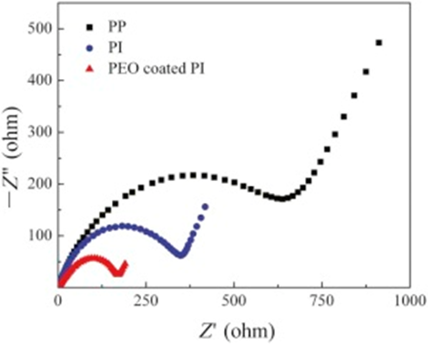 | Fig. 14. Impedance spectra of cell Li | separator | Li with Celgard 2400, PI and PEO-coated PI membrane as separators at 0 ° C, respectively. |
The PEO-coated PI membrane was prepared by electrospinning method followed by dip-coating and drying. The porosity of the fibrous composite membrane after dip-coating was 90% with the average size of 4.1 µ m, which could benefit the holding capacity of electrolyte. It was concluded that semicrystal PEO could improve the ionic conductivity furthermore. The electrode-electrolyte interfacial resistance was an order of magnitude smaller than that of Celgard 2400. PEO-coated PI membranes showed excellent rate capabilities in wide temperature range, which was ascribed to the efficient ionic conduction of PEO coating since the glass transition temperature was around -60 ° C, with which the fast lithium ion transport could take place on the interface between electrodes and electrolyte in the cell. It could be presumed that it is an ideal candidate for lithium-ion battery separator to achieve better battery performance.
The authors thank the financial support from the National Natural Science Foundation of China (Grant No. 51572174).
The authors have declared that no competing interests exist.
| [1] |
|
| [2] |
|
| [3] |
|
| [4] |
|
| [5] |
|
| [6] |
|
| [7] |
|
| [8] |
|
| [9] |
|
| [10] |
|
| [11] |
|
| [12] |
|
| [13] |
|
| [14] |
|
| [15] |
|
| [16] |
|
| [17] |
|
| [18] |
|
| [19] |
|
| [20] |
|
| [21] |
|
| [22] |
|
| [23] |
|
| [24] |
|
| [25] |
|
| [26] |
|
| [27] |
|
| [28] |
|
| [29] |
|
| [30] |
|