
Microstructure and Mechanical Properties of 06Cr13Ni4Mo Steel Treated by Quenching-Tempering-Partitioning Process
[Yuanyuan Song1, 2  , Jingping Cui
1 , Lijian Rong1, 2 ]
, Jingping Cui|
|


A heat treatment process, quenching-tempering-partitioning (Q-T-P), has been applied to a low carbon martensitic stainless steel 06Cr13Ni4Mo. By using this process, ultrafine reversed austenite can be obtained at room temperature. The microstructures of the reversed austenite and the martensite matrix were characterized by transmission electron microscopy (TEM) and energy dispersive spectroscopy (EDS) in detail. The results show that the ultrafine reversed austenite is enriched in Ni resulting in the austenite stability at room temperature. Two new types of nano-scale carbide precipitates are found in the martensite matrix. Detailed analysis suggests that the two nano-scale precipitates can be identified as ω phase and λ phase carbides, respectively. The orientation relationship between the ω phase and matrix is, while that between the λ phase precipitate and matrix is
. For the present steel, the ultrafine reversed austenite and carbide precipitates obtained by Q-T-P treatment provide a good combination of high strength and toughness.
The amount and stability of retained or reversed austenite at room temperature is of critical importance for improving the ductility and toughness of steels by the transformation-induced plasticity (TRIP) effect[1, 2]. The chemical composition of strong austenite stabilizers such as C or Ni has a great influence on its stability. Especially for the martensitic stainless steels such as Fe-Cr-Ni-C system, the phenomenon occurring during austenite reversion is complex due to the high content of alloying elements[3]. For low carbon martensitic stainless steel 06Cr13Ni4Mo, conventional quenching and tempering heat treatments have long been applied to produce the reversed austenite[4, 5, 6, 7]. It has been confirmed that the reversed austenite can only be obtained in the intercritical tempering temperature range of 580-650 ° C (slightly above the austenite start temperature As), where the local Ni enrichment is sufficient to stabilize the reversed austenite during cooling to room temperature[6]. When the tempering temperature is higher, the reversed austenite is unstable at room temperature due to the dilution of Ni. This will lead to the decrease in strength of materials and even cannot meet the requirement for ductility although it is improved during tempering resulting from dislocation recovery and so on[8].
In the present study, we propose a novel treatment termed as the quenching-tempering-partitioning (Q-T-P) in order to provide another way to produce reversed austenite-containing microstructures. In this new treatment, the as-quenched alloy was tempered at higher temperature to provide a martensitic-austenitic mixed microstructure. Then the partitioning temperature was chosen to be at a lower temperature to ensure more Ni to segregate to the local reversed austenite[4]. The morphology and chemical composition of the reversed austenite and martensite obtained by the novel process were characterized by using transmission electron microscopy (TEM) and energy dispersive spectroscopy (EDS). As will be shown below, this process could generate microstructures of both ultrafine reversed austenite and the martensite with high density of dislocation. And there exists two types of nano-scale precipitates at room temperature, which are identified to be the ω phase and λ phase, respectively, as reported in Ref. [9, 10]. Usually, the ω phase is widely studied in numerous group IV and V transition metals such as Ti and their alloys[11, 12], which exists in the metastable bcc-type β phase through phase transformation during cooling or under static/dynamic pressure[13, 14]. The crystal lattice of the ω phase is coherent with the bcc lattice and has hexagonal lattice parameters of 
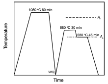
The experimental material used in this study is 06Cr13Ni4Mo steel and the chemical composition is Fe-0.05C-11.36Cr-3.84Ni-0.46Mo-0.5Mn-0.008P-0.002S (in wt%). The transformation temperatures As and Af (austenite start and finish temperatures) of this steel are approximately 580 ° C and 807 ° C, respectively[6]. The alloy ingot was prepared by vacuum melting and casting. The cast ingot was forged to a slab of 35 mm in thickness and then hot rolled to 12 mm thick plate using several passes with an average reduction ratio of 10% per pass. The samples of 10 mm × 12 mm × 12 mm in size cut from the hot-rolled plate were homogenized and austenitized at 1050 ° C for 1 h and water quenched. A sample of 0.1 mm × 10 mm × 10 mm in size was prepared for the in-situ high temperature X-ray diffraction (HT-XRD) studies performed on the Bruker D8 Discovery diffractometer (Cu-Kα radiation, λ = 0.154056 nm). The as-quenched sample was heated to 680 ° C at 1 ° C/s and held for 30 min, and then subsequently cooled to 580 ° C at 1 ° C/s and held for 45 min. After that, the specimen was cooled to room temperature at 2 ° C/s. The heat treatment route was schematically shown in Fig.1. The HT-XRD data were collected at each step and the volume fraction of reversed austenite was calculated according to the following equations.
Vγ +Vα =1(1)
Vγ =1.4Iγ /(Iα +1.4Iγ ) (2)
where Vγ and Vα are the volume fractions of austenite and martensite, respectively, andIγ and Iα are the integrated intensities of (111)γ and (110)α peaks, respectively[15]. Thin foil was prepared for transmission electron microscopy (TEM) analysis by means of ion milling. A JEOL 2100F microscope equipped with energy dispersive spectroscopy (EDS) operated at 200 kV was used to observe the microstructure.
 | Fig.1 Schematic diagram of the heat treatment route. |
The samples after the same austenitization mentioned above were subjected to tempering and partitioning treatment, i.e. the as-quenched samples were tempering at 680 ° C for 2 h, and then directly cooled to 580 ° C for 2 h for partitioning. For comparison, the conventional treatment of quenching + tempering + tempering (Q-T-T) was also carried out, i.e. the as-quenched samples were tempered at 680 ° C for 2 h and air-cooled to room temperature, and then heated to 580 ° C for 2 h, followed by air cooled to room temperature. The room temperature tensile and standard Charpy V-notch impact specimens were prepared from the as-treated samples, and their dimensions are 4 mm in width × 2 mm in thickness × 15 mm in gauge length and 10 mm × 10 mm × 55 mm, respectively.
Fig.2 shows the in-situ HT-XRD spectrum of the samples under different heat treatment processes. It can be seen that no peak of the retained austenite was found from the as-quenched sample, which is in agreement with our previous results[5]. When the sample was heated to 680 ° C, the peak of the reversed austenite was obvious and about 48% reversed austenite could be obtained, which was not decreased when the sample was cooled to 580 ° C. The shift of the peaks to higher 2θ position during cooling is attributed to the thermal contraction. When the sample was cooled to room temperature, it is noticeable that the peak of the reversed austenite can still be observed. This indicates that some reversed austenite is stable and remains untransformed to martensite during cooling. The volume fraction of the stable reversed austenite at room temperature is about 8%. Nearly half martensite is fresh, which is directly transformed from the austenite during cooling. The newly formed martensite is considered to have a high density of dislocation.
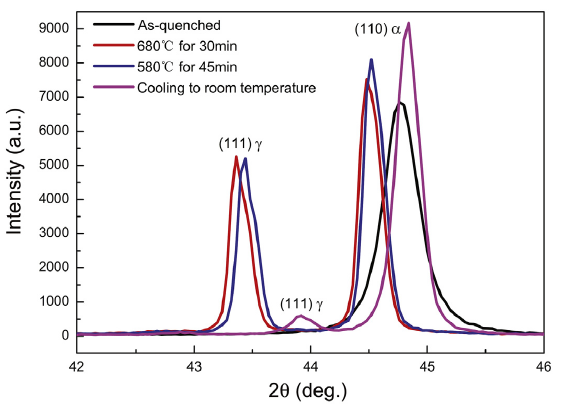 | Fig.2 In situ HT-XRD patterns of the sample at the as-quenched state, 680 ° C for 30 min, 580 ° C for 45 min and room temperature, respectively. |
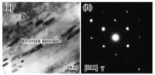
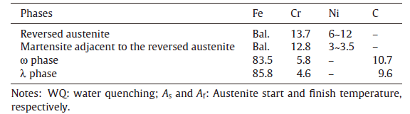
Fig.3 shows the typical TEM images of the reversed austenite in the sample after Q-P-T treatment. The ultrafine reversed austenite laths in a [011] orientation shown in Fig.3(a) are identified by electron diffraction in Fig.3(b) and the reversed austenite size is of several hundreds of nanometers. Furthermore, some ultrafine reversed austenite coexisted with the M23C6 carbides along the martensite lath boundaries were also observed in the sample, which are in agreement with that in Ref. 4. Table 1 summarized the weight concentrations of Fe, Cr and Ni in the reversed austenite and martensite matrix by means of TEM-EDS. The average Ni concentrations in the reversed austenite are in the range of 6-12 wt% and that in adjacent martensite is about 3 wt%. The results indicate that the partitioning of Ni occurs during the Q-T-P heat treatment.
 | Fig.3 TEM micrograph (a) and SAED pattern (b) of the reversed austenite in the sample after tempered at 680 ° C for 30 min plus 580 ° C for 45 min. |
| Table.1 EDS results of the chemical composition of the main alloy elements in each phase (in wt%) |
The stability of the reversed austenite is due to the partitioning of Ni during the Q-T-P heat treatment. At the tempering temperature 680 ° C, about 48% reversed austenite (as shown in Fig.2) can be obtained by the reverse martensitic transformation. At this time, the Ni concentration of the reversed austenite is insufficient to stabilize the reversed austenite upon cooling to room temperature[6]. No austenite can be retained when the sample is directly cooled to room temperature from 680 ° C[6]. When the sample with a martensite-austenite mixture is then isothermally held at 580 ° C for 45 min, it is assumed that there will be a driving force for Ni partitioning from the martensite to the pre-existed reversed austenite by diffusion[16]. Thus there will be more chances for the pre-existed reversed austenite to be enriched with Ni. Therefore some reversed austenite with sufficient Ni can be stable and obtained at room temperature.
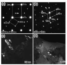
The microstructure characterization of the martensite matrix was also investigated by TEM. It is interesting to note that there are two new iron carbides present in the matrix.Fig.4(a) and (b) shows the typical selected area electron diffraction (SAED) patterns, while the corresponding dark field images are presented in Fig.4(c) and (d). Based on a recent study[8], the present diffraction pattern can be indexed as the martensitic matrix phase and ω phase with a hexagonal structure. The lattice parameters of the ω phase are: 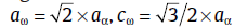

 | Fig.4 ω phase in the steel and the typical SAED patterns from the ω phase (a) and (b); corresponding dark field image of the ω phase (c) using the arrowed diffraction spot shown in (a); corresponding dark field image (d) using the arrowed diffraction spot shown in (b). |
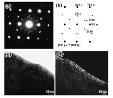
Fig.5 shows the SAED patterns obtained at an interface of the martensite matrix and another new phase (we call it the λ phase in this paper). The new phase can be indexed as a hexagonal close packed crystal structure based on the results of Tirumalasetty et al., who determined the crystal structure of the precipitate by TEM in a TRIP assisted steels[10]. The electron beam is parallel to the [110] crystallographic axis of the martensite matrix and the [0001] axis of the λ phase. The clear reflections from the matrix and the precipitates are shown schematically inFig.5(b). A dark-field image using 

 | Fig.5 Typical SAED pattern from the λ phase and the matrix (a), schematic illustration revealing the diffraction spots (b); the corresponding bright and dark field image of the λ phase (c, d). |
Now the question arises that why such iron carbides like the ω phase and the λ phase precipitates can be generated in low carbon martensite stainless steels. Ping and Geng considered that the carbon helps to stabilize and promote the bcc-to-ω transformation in high carbon steels and the ω phase has low chance to form in low carbon steels[9]. However, Raghavan et al. observed the metastable ω phase formed in a duplex ferrite-martensite stainless steel with C content of 70 ppm[17]. Our results confirm that the ω phase can also precipitate in the low carbon steels. According to the discussion in Ref.[18], Hsiung and Lassila proposed the dislocation mechanism for the ω phase formation during shear deformation for Ti alloy. The ω phase could be generated by the glide of partial dislocations of type 1/3[111], 1/6[111] and 1/2[111], which are dissociated from 1/2[111] perfect dislocation in the bcc structure[18]. In our case, only a little of the reversed austenite was much more stable due to its higher Ni concentration. Most of the reversed austenite was transformed to martensite by shear mechanism during cooling to the room temperature after being tempered at 580 ° C. It is thought that a high density of dislocations in the grains could be produced during the cooling process.
In addition, Tirumalasetty et al. considered that the formation of λ phase precipitates could be a consequence of temperature and time of a given heat treatment[10]. Comparing with the results of Tirumalasetty et al., we conducted a similar heat treatment, i.e. intercritical annealing (tempering) plus isothermal holding. It is thought that the λ phase carbide precipitate could be formed as a result of particular heat treatment. The underlying cause of this microstructure remains unclear. The mechanisms for the formation of the two novel nano-scale precipitates need further works.
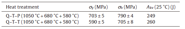
The room temperature tensile behavior and impact toughness of the samples after Q-T-P and Q-T-T treatments are shown in Table 2. The amount of the reversed austenite in the sample after Q-T-T treatment is about 10% calculated by the above formula. FromTable 2, it can be seen that the impact toughness of the samples after two kinds of treatments is nearly the same. The reason is that they contain nearly the same amount of the reversed austenite, which determined the impact toughness of the steel[5]. The strength of the sample after the Q-T-P treatment has been improved in comparison with that after the Q-T-T treatment. According to the above results, it is thought that the Q-T-P treatment could eventually lead to high density of dislocation in nearly half martensite, which contributes to the high strength. While in the sample after the Q-T-T treatment, all martensite are tempered where the dislocation has been recovered. In addition, the ω and λ carbide precipitates may lead to an increase in strength by precipitate-hardening.
| Table.2 Mechanical properties of the steel after different treatments. Q, T and P denote the quenching, tempering and partitioning, respectively. σ y, σ b and Akv indicate the yield strength (MPa), ultimate tensile strength (MPa) and impact toughness (J) |
(1)A Q-T-P heat treatment has been applied to a low carbon martensitic stainless steel 06Cr13Ni4Mo and an ultrafine reversed austenite can be obtained at room temperature by this process. The Ni partitions from the martensite phase to the reversed austenite, increasing the reversed austenite stability upon cooling to room temperature.
(2)The microstructures of this steel after Q-T-P treatment were characterized by TEM. The ultrafine reversed austenite in a size of several hundreds of nanometer and two nano-scale iron carbides are observed. Detailed analysis suggests that the two novel nano-scale precipitates can be identified as ω phase and λ phase, respectively. The Q-T-P treatment provides a good combination of high strength and toughness for this steel.
(3)The orientation relationship between the ω phase and matrix is 
The authors have declared that no competing interests exist.
| [1] |
|
| [2] |
|
| [3] |
|
| [4] |
|
| [5] |
|
| [6] |
|
| [7] |
|
| [8] |
|
| [9] |
|
| [10] |
|
| [11] |
|
| [12] |
|
| [13] |
|
| [14] |
|
| [15] |
|
| [16] |
|
| [17] |
|
| [18] |
|