

Tungsten Inert Gas Welding-Brazing of AZ31B Magnesium Alloy to TC4 Titanium Alloy
[Chuan Xu, Guangmin Sheng , Hui Wang, Ke Feng, Xinjian Yuan]
, Hui Wang, Ke Feng, Xinjian Yuan]
|
|


Tungsten inert gas (TIG) welding-brazing technology using Mg-based filler was developed to join AZ31B Mg alloy to TC4 Ti alloy in a lap configuration. The results indicate that robust joints can be obtained with welding current in the range of 60-70 A. The joint interface was found to be likely composed of Mg-Ti diffusion reaction layer accompanied with Mg17Al12 precipitate phase, indicating that metallurgical joining was achieved. The optimized joint with average tensile-shear strength of 190 N/mm2 was obtained and fracture occurred at the Ti/fusion zone interfacial layer during tensile test. Moreover, the fracture surface was characterized by equiaxed dimple patterns accompanied with a few lamellar tearing. Finally, finite element modeling (FEM) numerical simulation was developed to analyze the distribution characteristics of the temperature field of joints.
Titanium alloys, which are characterized by its extraordinary combination of high specific strength, excellent mechanical properties and good corrosion resistance, are used extensively in fields such as aerospace and aircrafts industries[1, 2]. Magnesium alloys, which are considered as the lightest family of the structural metals with a density of one-third of titanium alloys, are of great potential application in automobile industry for the sake of weight saving[3, 4, 5]. Currently, energy saving and ease of exhaust gas emission are important issues and must be urgently resolved. Since weight reduction of the energy consuming components such as vehicles and aircrafts is an effective approach, the joining of lightweight metallic alloys of magnesium to titanium alloys would be a promising approach to achieve this goal.
However, in spite of the great technological importance of Mg/Ti hybrid structure, it is quite challenging to achieve robust joining of Mg/Ti dissimilar alloys owing to the notable mismatch in physical and mechanical properties and lack of metallurgical compatibility[6]. The maximum solid solubility of Mg in Ti is 0.9 at.% and that of Ti in Mg is 0.02 at.%. The melting points of pure Mg and Ti are about 922 K and 1941 K, respectively. The tremendous difference in the melting points between these two kinds of metals causes the difficulty in melting them at the same time during fusion welding. Furthermore, the boiling point of Mg (1363 K) was much lower than the melting point of Ti (1941 K), indicating that the molten Ti will cause severe vaporization of Mg when they contact with each other. Therefore, the joining of dissimilar Mg/Ti alloys is difficult with commonly used fusion welding method in theory. Consequently, a wide spectrum of alternative joining techniques such as transient liquid phase (TLP) brazing[7, 8, 9], friction stir welding (FSW)[10, 11], laser keyhole welding[12, 13] and tungsten inert gas (TIG) welding-brazing[6] have been recently developed specific to the dissimilar joining Mg alloy to Ti alloy. Atieh and Khan[7, 8, 9] achieved TLP brazing of Mg and Ti alloys with double Ni and Cu sandwich foils. The ε phase (Mg), CuMg2 and Mg2Ni were observed and the maximum shear strength was 57 MPa. Existing literature reveals that FSW of Mg to Ti would result in the formation of Al-Ti intermetallic compounds, which tended to reduce the mechanical strength of joints[10, 11]. Furthermore, Gao et al. achieved Mg/Ti joining by laser keyhole welding with very strict control of laser offset from welding seam to Mg base plate[12, 13].
Of the joining techniques mentioned above, TIG welding-brazing is characterized by its advantages of high efficiency, flexibility, and excellent joining quality[14, 15, 16, 17]and offers a potential for the joining of dissimilar metals, which have tiny mutual solid solubility and great difference in melting point, e.g., Mg and steel[18, 19, 20]. The results showed that the sound joins were obtained. The maximum tensile-shear strength reached 270 N/mm2, representing 82.4% joint efficiency relative to the Mg alloy base metal[20]. In light of the above evidence, it is reasonable to expect that the welding-brazing technology would be applicable in Mg/Ti dissimilar joining as well, according to their similarities. However, few reports on the TIG welding-brazing of Mg to Ti can be found in the open literature so far.
In the present work, TIG welding-brazing of AZ31B Mg alloy to TC4 Ti alloy using AZ31B Mg alloy filler was performed. The microstructure, mechanical properties and fracture mechanism of the joint upon tensile-shear loading were studied and discussed by the experimental observations.
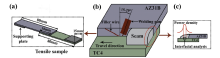
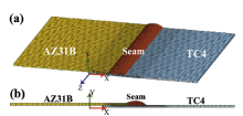
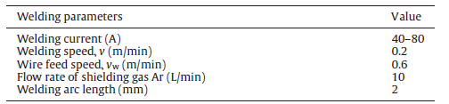
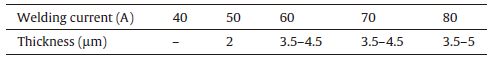
The experiments were performed with a TIG welding machine (YC-300WP5HGN). Commercially TC4 and AZ31B alloy plates with the same size of 80 mm × 50 mm × 1 mm were employed in the present study, and their chemical compositions are given in Table 1. An AZ31B Mg alloy wire with the diameter of 1.6 mm was chosen as the filler metal. Before welding, the overlapping surfaces were manually polished to remove the oxide film and subsequently assembled in the lap joint configuration with the Mg alloy plate placed on the top of Ti alloy, as shown in Fig.1. Argon gas was provided to prevent oxidation of the molten filler metal. Furthermore, the optimized welding parameters are shown in Table 2.
| Table.1 Chemical composition (wt%) of base metal |
 | Fig.1 Schematic diagram of TIG welding-brazing process and tensile test specimen. |
| Table.2 Experimental parameters used in the process |
After welding, the weldment was machined into a rectangular shape with the width of 15 mm. The specimens were tested on the electronic tensile testing machine with a travel speed of 1.5 mm/min and three specimens were tested for each set of parameter. The cross-sectional microstructures of Mg/Ti lap joints were analyzed by scanning electron microscope (SEM) in Back-scattered electron (BSE) mode with energy dispersive X-ray spectroscopy (EDS). The FEM numerical simulation was carried out by ABAQUS. In addition, the phase constituents at the fracture surface of joints were identified by X-ray diffraction (XRD).
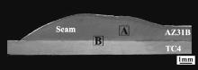
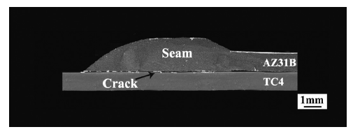
Fig.2 shows the cross-section of the typical Mg/Ti lap joints. Under the TIG heat source, all of the filler metals and Mg base metal were welded to form fusion welding zone and then fully spread on the Ti alloy surface to form a robust joint, as shown in area A. On the other hand, brazing occurred between the Mg-based filler metal and the Ti alloy plate, resulting in the formation of metallurgical reaction layer (MRL), as shown in area B.
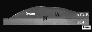 | Fig.2 Typical cross-section of Mg/Ti lap joint. |
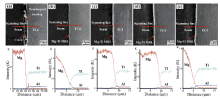
Fig.3 presents the BSE images of interfacial zone of Mg/Ti lap joints. The location in which the interfaces were observed is indicated in Fig.1. As shown in Fig.3(a), with the welding current of 40 A, a crack was clearly visible at the initial interface, and the interfacial layer was discontinuous and uneven. Table 3 shows the average thickness of interfacial diffusion reaction layer (DRL). However, with the welding current being increased to 50 A, an average of 2-µ m-thick interfacial diffusion reaction layer can be observed at the interfacial zone, as indicated in Fig.3(b). In addition, since temperature and reaction diffusion time of the interfacial zone increased with the increase of welding current, the average thickness of diffusion reaction layer gradually thickened from 3 to 5 µ m, as shown in Fig.3(c-e).
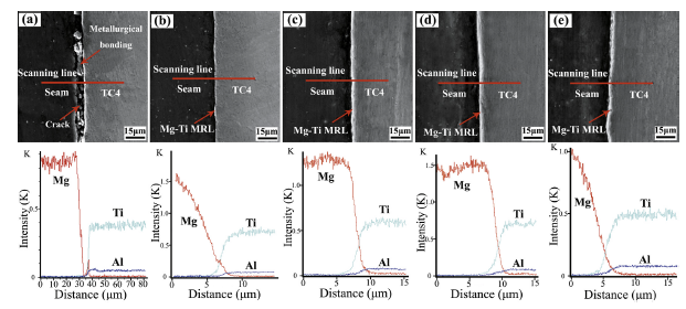 | Fig.3 SEM and EDS line scan results of interfacial zone of Mg/Ti lap joints with welding current: (a) 40 A, (b) 50 A, (c) 60 A, (d) 70 A, (e) 80 A (MRL, metallurgical reaction layer). |
| Table.3 Average thickness of interfacial reaction layer indicated in Fig.3 |
EDS line scan results of interfacial diffusion reaction layer are also shown in Fig.3. As shown in Fig.3(a), no element was detected in the crack, indicating that this area is indeed an unbonded region, which can be ascribed to the insufficient heat input. Therefore, the Mg/Ti assembly could only be partly metallurgically bonded with the welding current of 40 A. However, with the welding current in the range of 50-80 A, the Ti and Al contents gradually increased across the interface from seam to the Ti side, while the Mg content varied in the opposite direction. A thin Mg/Ti diffusion reaction layer was observed at the interfacial zone, which was indicative of the atom diffusion and interfacial reaction occurred despite the fast thermal cycle and short reaction time. The interfacial diffusion reaction layer would be discussed in other section. Note that the reaction layer exhibited a maximum thickness of 5 µ m and hence was below the critical thickness of 10 µ m[21]. Namely, the thin interfacial layer was beneficial to the joint strength.
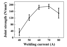
Fig.4 shows the joining strength of Mg/Ti lap joints. It can be found that the joints strength varied greatly with the variation of welding current, attributed to the change of interfacial microstructure. As shown in Fig.4, the Mg/Ti joint had poor joining strength with welding current of 40 A, which was caused by the lack of metallurgical bonding. However, as the welding current increased to 60-70 A, the joining strength was much higher and more stable. The average tensile-shear strength of optimized Mg/Ti joints was 190 N/mm2. However, with the welding current increased to 80 A, although the average tensile-shear strength of joints reached 148 N/mm2, the real results of each specimen fluctuated greatly because of the excessive vaporization of Mg alloy, indicating bad process stability. The reason will be further discussed combined with the FEM results in the discussion section. Actually, the process stability was also an important consideration, so the optimal welding current should be in the range of 60-70 A.
 | Fig.4 Joining strength of Mg/Ti lap joints. |
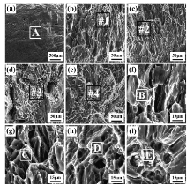
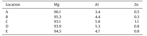
Fig.5 shows the representative fracture location of Mg/Ti lap joints. During the tensile test of Mg/Ti joints, the crack tended to initiate and propagate at the Ti/fusion interfacial layer, which was similar to that of laser welded-brazed Mg/Ti joint[12]. The characteristics of fracture surface correlated intimately to the welding current of joint. As shown in Fig.6(a), with the welding current of 40 A, the fracture surface of Mg side was quite smooth with the tensile-shear strength of 32 N/mm2. Obviously, it was a typical interfacial failure, due to the lack of sufficient metallurgical bonding. However, as the welding current increased to 50 A, the fracture surface was relatively smooth with a few scraggly areas, and the scraggly area was characterized by lamellar tearing patterns, as shown in Fig.6(b). Furthermore, with the welding current of 60 and 70 A, the fracture surfaces consisted of both scraggly and smooth areas, as shown in Fig.6(c and d). The scraggly area of the joint with extraordinary mechanical strength was characterized by equiaxed dimple patterns accompanied with a few lamellar tearing, which was similar to that of laser-welded AZ31B alloy[22]. Namely, the joint suffered plastic fracture upon tensile-shear loading.Table 4 shows the EDS results of area A-E pointed in Fig.6. Only Mg, Al, and Zn elements were detected at the fracture surface of Mg side, which was similar to that of Mg alloy base metal. The phase compositions of area A-E are likely composed of α -Mg and Mg17Al12phases[12]. In order to further confirm the phase composition, XRD analysis was performed at the fracture surface.
 | Fig.5 Typical fracture location of Mg/Ti joints. |
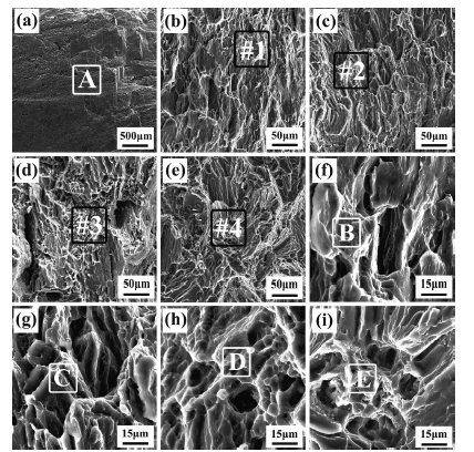 | Fig.6 Fracture surface of Mg/Ti lap joints: (a-e) fracture surface (seam side) of Mg/Ti joints with welding current of 40, 50, 60, 70, 80 A, (f-i) rectangle areas #1, #2, #3, #4 in (b-e), respectively |
| Table.4 EDS results of zone A-E indicated in Fig.6 (wt%) |
Fig.7 shows the XRD analysis results of the typical fracture surface. Theoretically, some Al-Mg or Al-Ti intermetallics were likely to be formed because the Al element can react with both Ti and Mg elements. However, it turned out that only the Mg, Ti and Mg17Al12phases were confirmed at the fracture surface of Ti side, as shown in Fig.7. Existing literature reveals that the formation of Ti3Al needed a delay time[12]. Ti3Al was hard to be formed during the welding process with fast solidification rate. In addition, during the welding process, the α -Mg phase was preferred and nucleated and then underwent rapid and non-equilibrium cooling process[18, 23, 24]. Eventually, the molten alloy was quickly solidified and cooled to room temperature. With the maximum solid solubility of Al decreasing immediately from 12.7 wt% to about 2.0 wt%, the residual Al would precipitate the Mg17Al12 phase. In addition, Mg and Mg17Al12 phases were confirmed at seam side, indicating that fracture occurred in the interfacial diffusion reaction layer, as shown inFig.7.
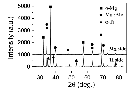 | Fig.7 XRD analysis of typical fracture surfaces of Mg/Ti joint with welding current of 70 A. |
In this work, Mg/Ti diffusion reaction layers accompanied with Mg17Al12 precipitate phase were formed at the interface of joint, which was the key to obtain the excellent joining strength.
A three-dimensional (3D) finite element model was implemented in the finite element software ABAQUS, as shown in Fig.8. The aim of FEM simulation was to determine the influence of heat input on the distribution characteristics of the temperature field of joints. In addition, FEM simulation results can explain the decrease of mechanical properties of joints with overlarge welding current. Because TIG welding-brazing has high heating/cooling velocity and high temperature gradient, fine mesh was generated near the seam zone and the coarse mesh was generated far from the seam zone, as shown inFig.8.
 | Fig.8 Meshed model with 3D block elements. |
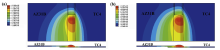
Fig.9 shows the temperature field of the TIG welding-brazing process. The simulation parameters are welding current of 70 and 80 A, welding speed of 0.2 m/min and wire feed speed of 0.6 m/min. The temperature field distribution exhibits an obviously asymmetric characteristic. High temperature area at the Mg side is wider than that of the Ti side, as shown in Fig.9. The reason is that the heat conductivity of Mg alloy outclasses that of Ti alloy.
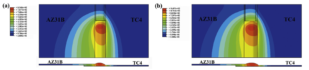 | Fig.9 Transient temperature field distribution with different welding current: (a) 70 A, (b) 80 A. |
As shown in Fig.9(a), with the welding current of 70 A, the temperature of weld seam center was 835 ° C, higher than the melting point of AZ31B Mg alloy (649 ° C) and resulted in the sufficient melting of Mg alloy base metal and filler metal. Hence, a thin diffusion reaction layer occurred at the interface of joints. On the other hand, the maximum surface temperature of TC4 Ti alloy was only 768 ° C, lower than the melting point of Ti alloy base metal (1668 ° C), which demonstrated the welding-brazing dual characteristic. However, as the welding current increased to 80 A, the maximum temperature of weld seam center and Ti alloy base metal increased to 950 ° C, which was quite close to the boiling point of Mg alloy (1090 ° C), as shown in Fig.9(b). Eventually, the high temperature of weldment resulted in the excessive vaporization of Mg alloy, which decreased the joining strength of joints.
(1)Robust joints were obtained with the optimal welding current of 60-70 A. And FEM numerical simulation results show that catastrophic vaporization of Mg alloy would occur with overlarge welding current of 80 A.
(2)A thin Mg-Ti interfacial diffusion reaction layer accompanied with Mg17Al12precipitate phase was found at the interface of the Mg/Ti joints with the thickness of 2-5 µ m, indicating that metallurgical bonding occurred between Mg alloy and Ti alloy.
(3)The average tensile-shear strength of optimized joint was 190 N/mm2 and fracture occurred at the Ti/fusion zone interfacial layer during tensile test.
(4)The fracture surface of optimized joint was characterized by equiaxed dimple patterns accompanied with a few lamellar tearing.
The authors have declared that no competing interests exist.
| [1] |
|
| [2] |
|
| [3] |
|
| [4] |
|
| [5] |
|
| [6] |
|
| [7] |
|
| [8] |
|
| [9] |
|
| [10] |
|
| [11] |
|
| [12] |
|
| [13] |
|
| [14] |
|
| [15] |
|
| [16] |
|
| [17] |
|
| [18] |
|
| [19] |
|
| [20] |
|
| [21] |
|
| [22] |
|
| [23] |
|
| [24] |
|