


Pinless Friction Stir Spot Welding of Mg‒3Al‒1Zn Alloy with Zn Interlayer
[R.Z. Xu1, 2 , D.R. Ni2 , Q. Yang2 , C.Z. Liu1 , Z.Y. Ma2  ]
]
]
|
|


With the addition of a thin Zn interlayer, 2.4 mm thick Mg‒3Al‒1Zn alloy sheets were friction stir spot welded (FSSW) using a pinless tool with flat, convex and concave shoulder shapes. The results showed that an alloying reaction took place between the Mg substrate and Zn interlayer during FSSW, forming a discontinuous intermetallics layer composed of dispersive (α-Mg + MgZn) eutectic structure underneath the shoulder and a Mg‒Zn intermetallics bonding zone at the outside of the joints. This alloying reaction increased the bonded area and eliminated the hook defects, thereby producing sound FSSW joints with a shallow keyhole without hook defects. The increase of plunge depth was beneficial to the Mg‒Zn diffusion, thereby increasing the tensile-shear load of the joints. However, excessive plunge depths resulted in a decrease of the effective sheet thickness, reducing the strength of the joints. At a small plunge depth, the convex and concave shoulders were more beneficial to the interface reaction than the flat shoulder. The maximum joint load of 6.6 kN was achieved by using the concave shoulder at a plunge depth of 1.0 mm. A post-welding heat treatment promoted the dissolution of the discontinuous reaction layer in the joints; however, it led to the occurrence of void defects, influencing the bonding strength.
Weight saving in the automotive industry is becoming increasingly important and can be realized by using lightweight structural materials, such as Mg alloys and Al alloys[1]. When these materials are used for structure construction, welding procedures are required[2, 3]. However, some defects such as porosity, oxidization, a wide heat-affected zone, and high residual stress, are often produced in conventional fusion welded joints[4, 5]. It is well known that spot welding is an important welding process in the automotive industry[2]. However, fusion spot welding of light alloys faces metallurgical problems similar to those associated with conventional fusion welding[6, 7].
As a solid state joining method, friction stir welding (FSW) is proven to be a potential welding technique for joining light alloys[8, 9, 10, 11, 12, 13, 14, 15]. Friction stir spot welding (FSSW) is a variant of FSW, and it is free of the defects commonly associated with fusion spot welding[16]. Therefore, there is much interest in FSSW of light alloys due to its great potential as a substitute for conventional spot welding techniques[17].
FSSW can also be called plunge FSSW or conventional FSSW (CFSSW), which has been applied in the spot welding of light alloys[18]. However, many studies have indicated that keyhole[19] and hook defects[20, 21] present in the FSSW joints, seriously reducing joint properties such as tensile-shear strength and fatigue strength[22, 23]. In order to eliminate the keyhole, refill FSSW (RFSSW) was developed[18]. A few studies indicated that the tensile-shear loads of the joints of light alloys could be improved by RFSSW due to the elimination of the welding keyhole[24, 25], but the equipment for the RFSSW process was extremely complex, and most of the hook defects could not be avoided, limiting the wide application of RFSSW in industry[26].
Subsequently, the pinless FSSW (P-FSSW) process was firstly proposed and applied on Al alloys[24]. P-FSSW has many advantages such as a simpler process and better appearance, with a shallow or no keyhole being retained. The P-FSSW Al alloy joints showed an increased tensile strength compared to the CFSSW joints, but the further increase of loads was limited due to the existence of hook defects[21, 24].
In fact, the hook defect is a partial metallurgical zone inside the FSSW joints and it is formed due to the flow of the heated and softened material underneath the shoulder at the plunging stage[27, 28]. In order to eliminate the hook defect of P-FSSW joints, a method that combined FSSW with subsequent FSW (FSSW-FSW) was proposed to weld Al alloys[26]. First, a P-FSSW Al alloy joint with a hook defect was produced using a pinless tool. Second, on the upper surface of the hook region, a circular FSW weld was produced using the pinless tool, obtaining a shallow nugget zone which covered the hook defect. In this case, the hook defect of the P-FSSW joint was eliminated. As a result, the joint load was significantly increased. However, the troublesome nature of the operation did not favor its wide application.
In addition to Al alloys, some efforts have been made on the P-FSSW of Mg alloys, but it proved to be difficult to realize a good bond due to the active behavior of Mg and the incomplete break-up of oxide film on the contact surface[29]. Therefore, reducing the formation of oxide film and promoting the interface reaction of the faying surface is a potential way to improve the joining quality of the P-FSSW Mg alloys.
In the previous investigations, it has been proven that a Zn interlayer could reduce the temperature of the interface reaction and improve the wettability of the faying surface during Mg alloy FSSW, thereby increasing the bonded area and eliminating hook defects at the same time, and increasing the bonding strength[30, 31]. Therefore, in this study, Zn was chosen as the interlayer material with the aim of realizing Mg alloy P-FSSW. The effect of the plunge depth and the end surface geometry of shoulders, as well as a post-welding heat treatment on the tensile-shear properties of the P-FSSW joints, were examined. In addition, the influencing mechanism of Zn interlayer addition on the microstructure of P-FSSW joints was investigated in detail.
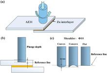
The substrate material used in the present study was 2.4 mm thick sheets of AZ31 Mg alloy with a composition of Mg‒3.02Al‒0.82Zn‒0.30Mn‒0.01Si (wt%). Pure Zn foil of 0.1 mm in thickness was used as the interlayer. The schematic of P-FSSW with the addition of a Zn interlayer is shown in Fig. 1(a).
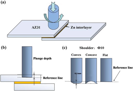 | Fig. 1. Schematics of P-FSSW with interlayer: (a) position of interlayer, (b) plunge depth, and (c) shoulder shapes. |
The welding tools are pinless and their shoulders are 10 mm in diameter with different flat, concave and convex shapes. All the P-FSSW operations with and without the interlayer were conducted at a tool rotational rate of 3000 r/min and a plunge rate of 2.5 mm/s. The dwell time was 5 s and the tool withdrawing rate was 30 mm/s at the end of each spot welding operation. The presupposed plunge depth was 1.0, 1.5, and 2.0 mm, respectively (Fig. 1(a) and (c)). A part of joints was treated in a vacuum furnace at 400 ° C for 60 min and then cooled to room temperature inside the furnace.
Specimens for microstructure examination were sectioned through the center of the joints and parallel to the loading direction. After being mechanically ground and polished, the specimens were etched with an etching reagent consisting of 4.2 g picric acid, 10 ml acetic acid, 10 ml H2O, and 70 ml ethanol. Microstructures were examined by optical microscopy (OM), scanning electron microscopy (SEM, LEO Supra 35) with an energy dispersive X-ray spectrometer (EDS, Oxford Instruments X-Max), and transmission electron microscopy (TEM, Tecnai F20). X-ray diffraction (XRD) analysis was conducted using CuKα radiation.
Lap-shear tensile specimens with a length of 100 mm, width of 30 mm and overlap area of 30 mm × 30 mm were electrical discharge machined from the FSSW joints. Lap-shear tensile tests were conducted using a Zwick/Roell Z050 tester at a speed of 1 mm/min. The load values for each condition were calculated by averaging three test results. The fracture surfaces were examined by OM and SEM.
The AZ31 Mg sheets were subjected to P-FSSW using the flat shoulder without Zn interlayer at different plunge depths of 1.0, 1.5, and 2.0 mm. It was found to be difficult to bond the sheets together. Fig. 2(a) shows the top view of a P-FSSW joint with a plunge depth of 1.5 mm. A shallow keyhole was detected on the top surface and a little flash appeared on its periphery. However, the faying surface between the two sheets was not bonded at all (Fig. 2(b) and (c)). EDS analysis of the joint interface revealed that region A consisted of 89.3 at.% Mg and 10.7 at.% O (Fig. 2(d)), indicating that the sheet interface was severely oxidized.
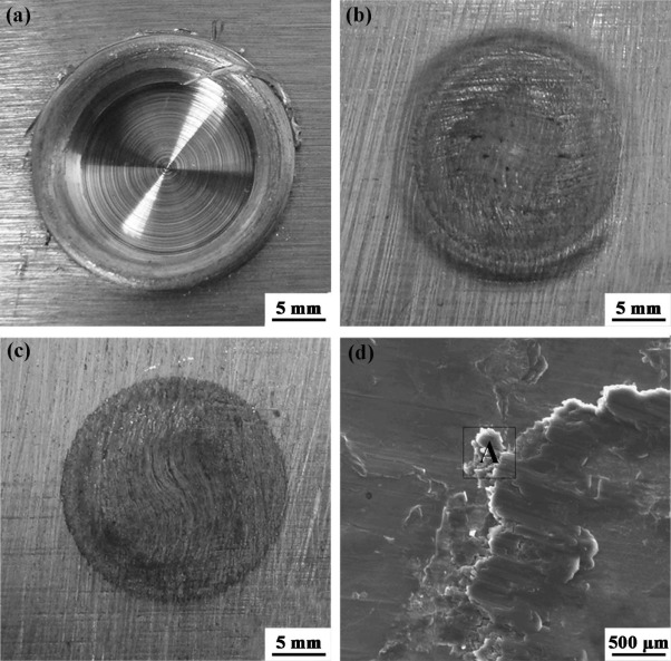 | Fig. 2. (a) Top and (b) bottom views of top sheet of AZ31 P-FSSW without Zn interlayer at plunge depth of 1.5 mm, (c) typical view of bottom sheet and (d) microstructure of bonding area. |
3.2.1. Influence of plunge depth on P-FSSW AZ31 joint
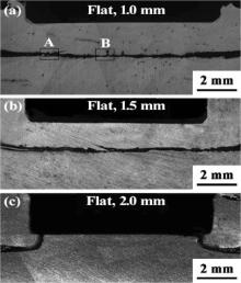
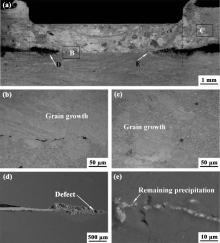
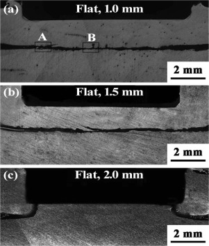
Fig. 3(a) shows a typical cross-section photograph of the P-FSSW AZ31 joint using the flat shoulder at a plunge depth of 1.0 mm. It was found that the Mg sheets were successfully joined. The magnified microstructures of regions B-E (Fig. 3(a)) exhibited that the grain sizes on the top of the residual Mg‒Zn reaction layer were refined slightly (Fig. 3(c)-(e)) compared to those of the substrate (Fig. 3(b)), indicating the occurrence of dynamic recrystallization in these zones during P-FSSW.
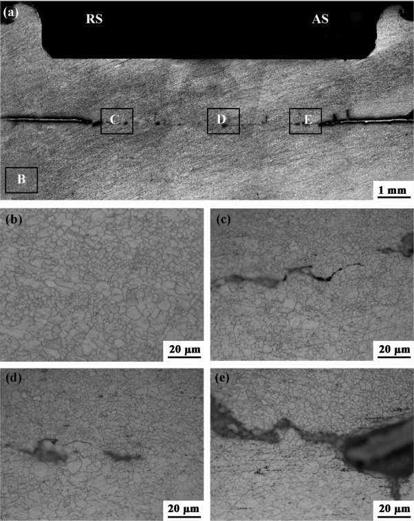 | Fig. 3. (a) Typical cross-section photograph of P-FSSW AZ31 joint welded with flat shoulder at plunge depth of 1.0 mm and microstructures of (b) region B, (c) region C, (d) region D, and (e) region |
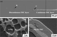
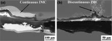
Fig. 4(a) shows a typical SEM photograph on the advancing side (AS) in the P-FSSW AZ31 joint. A continuous Mg-Zn reaction layer appeared on the keyhole periphery, increasing the bonding area of the joint significantly. The thickness of the reaction layer decreased from the periphery to the center of the joint. In addition, the reaction layer exhibited a discontinuous distribution due to the more adequate reaction between the Mg substrate and Zn interlayer at the center of the joint (Fig. 4(a) and (b)). Furthermore, the hook defect was eliminated by the formation of the Mg‒Zn intermetallics (Fig. 4(a) and (c)).
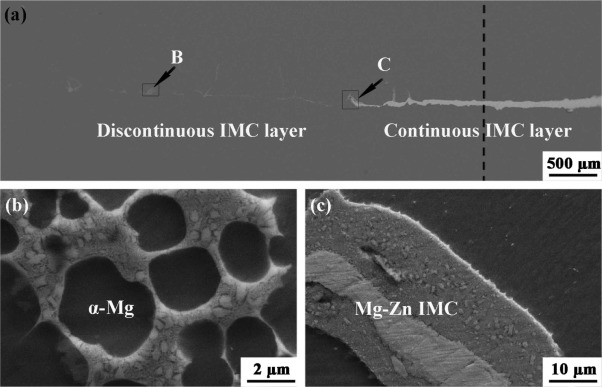 | Fig. 4. (a) Magnified photograph of advancing side in P-FSSW AZ31 joint welded with flat shoulder at plunge depth of 1.0 mm (black dotted line: extension line of the shoulder end surface) and microstructures of (b) region B and (c) region C. |
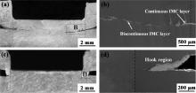
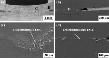
Fig. 5(a) shows a typical cross-section photograph of the P-FSSW AZ31 joint using the flat shoulder at a plunge depth of 1.5 mm. The length of the continuous Mg‒Zn reaction layer decreased with increasing the plunge depth (Fig. 3 and Fig. 5), revealing that a large plunge depth was beneficial to the bonding of AZ31 sheets. With further increasing the plunge depth to 2.0 mm, the continuous Mg‒Zn reaction layer underneath the shoulder almost disappeared. However, a hook region appeared outside the shoulder (Fig. 5(c) and (d)).
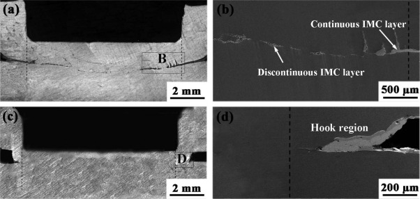 | Fig. 5. Typical cross-section photographs of P-FSSW AZ31 joints welded with flat shoulder at plunge depths of (a) 1.5 mm and (c) 2.0 mm, and microstructures of (b) region B and (d) region D (black dotted lines: extension lines of the shoulder end surface). |
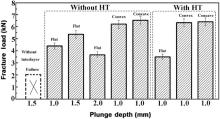
Fig. 6shows the tensile-shear fracture load of various joints. The fracture load of the joint welded with the flat shoulder at a plunge depth of 1.0 mm reached about 4.5 kN, which is superior to that of other joints obtained by the tool with a pin (shoulder 10 mm in diameter), as shown in References [20, 30-36]. With increasing plunge depth, the fracture load first increased and then decreased. At the plunge depth of 1.5 mm, the maximum load of the joint reached 5.5 kN. With increasing the plunge depth to 2.0 mm, the fracture load of the joint decreased to about 3.8 kN.
 | Fig. 6. Tensile-shear loads of P-FSSW AZ31 joints under various welding processes and heat treatment (HT). |
Fig. 7(a)-(c) shows the typical fracture locations of the above three joints, respectively. It can be seen that fracture of the joints welded with plunge depths of 1.0 and 1.5 mm occurred along the interface between the top and bottom sheets. The magnified microstructure of the fracture locations (zones A and B in Fig. 7(a)) reveals that the fracture of the joint occurred along the orientation of the continuous reaction layer (Fig. 8(a) and (b)). However, for the joint at the plunge depth of 2.0 mm, the fracture occurred toward the shallow keyhole due to the decrease of the effective sheet thickness (Fig. 7(c)).
 | Fig. 7. Typical fracture locations of P-FSSW AZ31 joints welded with flat shoulder at plunge depths of (a) 1.0 mm, (b) 1.5 mm and (c) 2.0 mm. |
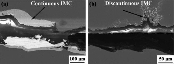 | Fig. 8. Magnified photographs of (a) region A and (b) region B in Fig. 7(a). |
3.2.2. Influence of end surface geometries on P-FSSW AZ31 joint
From Fig. 6, it is clear that appropriate increase of the plunge depth can increase the joint load to some extent, but this will result in significant increase of the keyhole depth on the top sheet, as shown in Fig. 5, thereby decreasing the effective sheet thickness. Therefore, solely increasing the plunge depth is not an optimum choice to enhance the joint strength. Alternatively, different end surface geometries of shoulders were used with the aim of increasing the joint load at the low plunge depth of 1.0 mm.
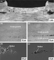
Fig. 9(a) shows a typical cross-section photograph of the P-FSSW AZ31 joint using the convex shoulder at a plunge depth of 1.0 mm. It was found that a good bond between the Mg sheets was realized. Some small discontinuous Mg‒Zn intermetallics were detected underneath the shoulder (Fig. 9(b) and (c)). In addition, a continuous Mg‒Zn reaction layer was formed on the periphery of the shallow keyhole rather than underneath the shoulder (Fig. 9(a) and (b)), thus increasing the bonded area of the joint.
 | Fig. 9. (a) Typical cross-section photographs of P-FSSW AZ31 joint welded with convex shoulder, and microstructures of (b) region B and (c) region C in 9(a); microstructures of (d) region D in 9(b) (black dotted lines: extension lines of the shoulder end surface). |
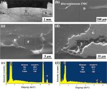
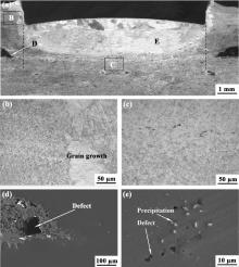
Fig. 10(a) shows a typical cross-section photograph of the P-FSSW AZ31 joint using the concave shoulder at a plunge depth of 1.0 mm. Similar to the joint using the convex shoulder, some small discontinuous Mg‒Zn intermetallics were also detected underneath the shoulder and distributed along the joint interface (Fig. 10(b) and (c)). In addition, the hook region was transferred to the outside of the shallow keyhole and displaced by the Mg‒Zn reaction layer (Fig. 10(a), (b) and (d)).
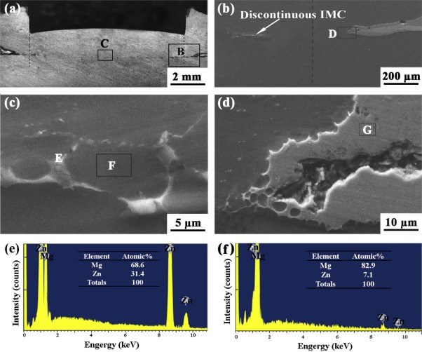 | Fig. 10. (a) Typical cross-section photographs of P-FSSW AZ31 joint welded with concave shoulder, and microstructures of (b) region B and (c) region C in 10(a); microstructures of (d) region D in 10(b); EDS spectra obtained from regions (e) E and (f) F in (c) (black dotted lines: extension lines of the shoulder end surface). |
The tensile-shear testing showed that the fracture loads of the above two joints produced using the convex and concave shoulders reached about 6.4 and 6.6 kN, respectively (Fig. 6). Despite the fracture mode similar to that of the joint using the flat shoulder at the plunge depth of 1.0 mm (Fig. 11(a)-(c)), the elimination of hook defects, the formation of a discontinuous intermetallics layer and the increase of the bonded area resulted in the further increase of strength of the joints welded with the convex and concave shoulders (Fig. 6).
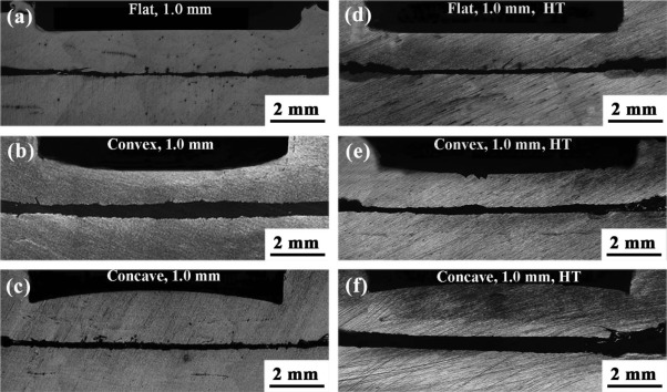 | Fig. 11. Typical fracture locations of P-FSSW AZ31 joints at a plunge depth of 1.0 mm using the different shoulders with or without post-weld heat treatment (HT): (a) flat, (b) convex, (c) concave; (d) flat, HT, (e) convex, HT, (f) concave, HT. |
3.2.3. Influence of post-welding heat treatment on P-FSSW AZ31 joint
Fig. 12(a) shows a typical cross-section photograph of the heat treated P-FSSW AZ31 joint welded with the flat shoulder at a plunge depth of 1.0 mm. The grain size was abnormally increased on the top of Mg‒Zn reaction layer and the periphery of the shallow keyhole (Fig. 12(b) and (c)). In addition, some small Mg-Zn phases could also be detected at the center of the joint (Fig. 12(e)), indicating that the diffusion reaction between the Mg substrate and Zn interlayer was not sufficient. At the same time, the heat treatment did not decrease the thickness and length of the continuous Mg‒Zn intermetallics at the periphery of the keyhole (Fig. 3 and Fig. 12), but it tended to generate more defects (Fig. 12(d)).
 | Fig. 12. (a) Typical cross-section photograph of P-FSSW AZ31 joint welded with flat shoulder at plunge depth of 1.0 mm and the microstructures of (b) region B, (c) region C, (d) region D and (e) region E after HT (black dotted lines: extension lines of the shoulder end surface). |
Fig. 13(a) shows a typical cross-section photograph of the heat treated P-FSSW AZ31 joint welded with the convex shoulder at a plunge depth of 1.0 mm. The area of abnormal grain growth was much smaller than that of the joint welded with the flat shoulder (Fig. 12 and Fig. 13). At the same time, it was noticed that abnormal grain growth of the hook region was also obvious (Fig. 13(a) and (c)). In addition, some intermetallics with a large size were not dissolved completely in the joint, and some small void defects appeared due to the intense diffusion reaction (Fig. 13(e)). Furthermore, the defects of the hook region were also increased due to the intense diffusion reaction (Fig. 13(d)).
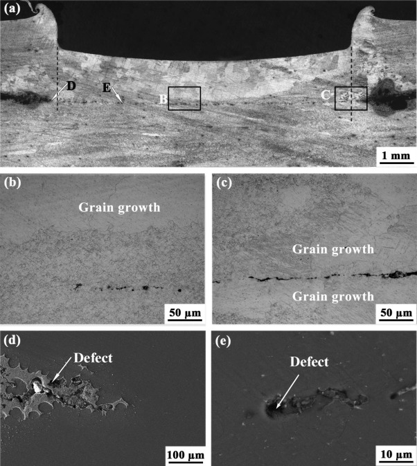 | Fig. 13. (a) Typical cross-section photograph of P-FSSW AZ31 joint welded with convex shoulder at plunge depth of 1.0 mm and microstructures of (b) region B, (c) region C, (d) region D and (e) region E after HT (black dotted lines: extension lines of the shoulder end surface). |
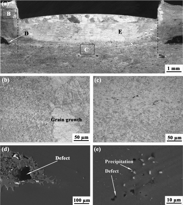 | Fig. 14. (a) Typical cross-section photograph of P-FSSW AZ31 joint welded with concave shoulder at plunge depth of 1.0 mm and microstructures of (b) region B, (c) region C, (d) region D and (e) region E after HT (black dotted lines: extension lines of the shoulder end surface). |
The tensile-shear testing showed that the fracture mode of the joints after heat treatment was similar to that before heat treatment (Fig. 11). For the P-FSSW AZ31 joint welded with the flat shoulder at the plunge depth of 1.0 mm, the heat treatment did not increase the joint fracture load and conversely resulted in a marked decrease (Fig. 6). For the P-FSSW AZ31 joints welded with the concave and convex shoulders at the plunge depth of 1.0 mm, the fracture loads of joints did not exhibit a significant change after the heat treatment.
3.2.4. Microstructure evolution of P-FSSW AZ31 joint with Zn interlayer
In order to reveal the microstructure and phase compositions on the interface between the Mg substrate and the Zn interlayer, the P-FSSW joint welded with the concave shoulder at the plunge depth of 1.0 mm, exhibiting the highest fracture load, was further investigated by XRD, SEM with EDS, and TEM.
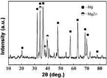
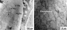
The XRD results indicated that the interface zone of the joint was mainly composed of α -Mg and MgZn (Fig. 15). The composition of regions E, F and G in Fig. 10 was analyzed with EDS. The results showed that region E consisted of 68.6 at.% Mg and 31.4 at.% Zn (Fig. 10(e)). According to the Mg‒Zn phase diagram[37] and the EDS and XRD results, region E should be the (α -Mg + MgZn) eutectic structure. Region F with a composition of 7.1 at.% Zn and 82.9 at.% Mg should be α -Mg (Fig. 10(f)). The microstructure and composition (69.3 at.% Mg and 30.7 at.% Zn) of region G were similar to those of region E.
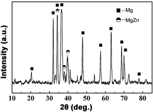 | Fig. 15. XRD pattern of interface between Mg substrate and Zn interlayer in the joint welded with concave shoulder at plunge depth of 1.0 mm. |
TEM images of the intermetallics at the center of the joint show that a lamellar (α -Mg + MgZn) eutectic structure was distributed on the boundary of the α -Mg solid solution (Fig. 16(a) and (b)). The EDS result reveals that the gray zone was α -Mg while the dark strip was MgZn. Therefore, the above results further proved that the discontinuous layer of intermetallics was composed of (α -Mg + MgZn) eutectic structure and α -Mg solid solution.
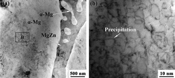 | Fig. 16. TEM microstructure at the center of joint showing (a) eutectic structure and (b) magnified view of region B in (a). |
For Mg alloys, several attempts have proven that the keyhole, unbonded zone and hook defects[15] presented in the CFSSW joints, as shown in Fig. 17(a), seriously reducing the joint properties. Although the RFSSW process could refill the keyhole[39, 40], thereby increasing the joint fracture load, the hook defect and unbonded zone still remain in the joint (Fig. 17(b)), limiting further increase of the joint fracture load. The previous studies proved that the incomplete break-up of the Mg oxide film led to the formation of hook defects and an unbonded zone[27, 28, 30, 31]. At the same time, the oxide film also increased the difficulty of bonding between the top and bottom sheets for Mg alloy P-FFSW (Fig. 2).
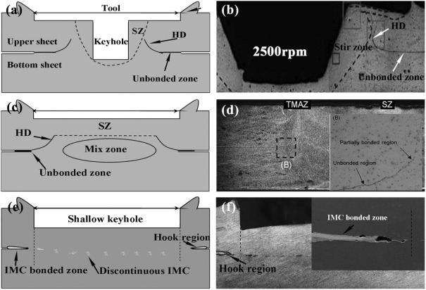 | Fig. 17. (a, c, e) Schematic diagrams and (b, d, f) macrographs of joints using different FSSW technologies: (a, b) CFSSW joint with a pin[25], (c, d) RFSSW joint[38] and (e, f) P-FSSW joint (present work). |
However, adding a pure Zn interlayer between two welded Mg sheets prior to the welding operation solved the above problems. This was because the Zn interlayer reacted with the Mg substrate to form the Mg‒Zn intermetallics and dissolved the oxide film of the faying surface[30, 31, 41, 42], promoting the bonding of sheets and thereby eliminating the hook defects and increasing the bonded area of the joint at the same time (Fig. 17(c)). As a result, the load of the joints was increased (Fig. 6).
In other words, the addition of the Zn interlayer played an important role in promoting the bonding of the interface between the two sheets based on the above results. During the P-FSSW process the rotating shoulder plunged into the top sheet of the Mg alloy, producing heat and pressure. Then, the welding temperature on the joint interface was increased by keeping the rotating shoulder in contact with the top sheet. The difference of the temperature and pressure led to variation of the extent of the reaction between Mg and Zn from the periphery to the center of the P-FSSW joint. According to the Mg‒Zn binary phase diagram[34], when the heat and pressure were sufficient, most of the Zn interlayer with a low melting point could diffuse into the Mg substrate (Fig. 9 and Fig. 10). With decrease of the temperature, Mg7Zn3 phase was formed by the eutectic reaction of L→ α -Mg + Mg7Zn3at 340 ° C. Subsequently, with further decrease of the temperature, MgZn phase was eventually generated by the eutectic reaction of Mg7Zn3→ α -Mg + MgZn at 325 ° C (Fig. 16). However, when the heat and pressure were insufficient, the Zn interlayer reacted with the Mg substrate to form a continuous diffusion reaction zone composed of Mg-Zn intermetallics (Fig. 4(a) and (b)).
Clearly, the alloy reaction between the Zn interlayer and the Mg substrate significantly reduced the temperature of the interface reaction. At the same time, the interface reaction at a low temperature could also lower the oxidation of the Mg surface. In this case, sound P-FSSW AZ31 joints without the hook defect were produced. Therefore, the tensile-shear fracture loads of P-FSSW joints are much higher than those of CFSSW Mg joints (Table 1).
| Table 1 Summary of tensile shear data for various FSSW Mg alloy joints prepared under a variety of FSSW conditions (10 mm in shoulder diameter) |
Based on the above results, sound P-FSSW joints of Mg alloys could be achieved with the addition of a Zn interlayer. For the P-FSSW of Mg alloys, the increase of the plunge depth promoted the Mg‒Zn diffusion reaction and increased the length of the discontinuous reaction layer (Fig. 3, Fig. 4 and Fig. 5), which is beneficial to enhancing the bonding strength. However, an excessive plunge depth led to increase of the keyhole depth and decrease of the effective sheet thickness (Fig. 5(c)), thus reducing the joint strength (Fig. 6).
In FSSW, different shapes of the shoulders directly affect the flow behavior of the material[20, 25]. Because the grain size in the zone of severe plastic deformation was more easily grown under the same heat treatment process, the influence of shoulder shape on the plastic deformation of the Mg alloy substrate could be identified indirectly by the area and location of abnormal grain growth after post-welding heat treatment. Based on the above analysis, the area of plastic deformation induced by the flat shoulder was the largest (Fig. 12) and that by the concave shoulder was the smallest (Fig. 14).
For the flat shoulder, the design is the simplest, but it is not effective for trapping the flowing material under the bottom of the shoulder[33, 43]. Therefore the heated and softened material underneath the shoulder was forced upward and outward, leading to an obvious plastic deformation on the periphery of a shallow keyhole (Fig. 12), which resulted in heat loss. In addition, with increasing holding time, the heat input could increase at the initial stage, but the decrease of the friction force between the top sheet and the shoulder may result in an obvious slowing in the rate of temperature increase at the subsequent stage[36]. Therefore, the flat shoulder is unhelpful to the accumulation of heat and maintaining of pressure, leading to the vast difference in the extent of reaction at the center and at the edge of the joint (Fig. 3 and Fig. 5).
For the convex shoulder, the protruded tip of the shoulder could play a positive role in increasing the plunge depth (Fig. 3 and Fig. 9). In addition, the heated and softened material with a high temperature underneath the center zone of the convex shoulder was easier to push away from the center to the periphery of the convex shoulder, but the convex shoulder could keep a contact with the workpiece at any location along the convex end surface[33]and[44], assisting the thermal conduction and pressure between the shoulder tip and interface. In addition, the obvious plastic deformation at the hook region also proved that the convex shoulder could form a pressure toward the keyhole periphery (Fig. 13(a) and (c)), which was beneficial to the interface reaction between the Zn interlayer and the Mg substrate at the periphery of the joint (Fig. 9(a) and (b)). As a result, the extent of the reaction of the joint welded with a convex shoulder at the plunge depth of 1.0 mm was even better than that of the joint welded with a flat shoulder at the plunge depth of 1.5 mm (Fig. 5 and Fig. 9). In brief, the convex shoulder could supply a large welding pressure compared to the flat shoulder, assisting the bonding between the top and bottom sheets.
For the concave shoulder, it could serve as an escaping volume for the heated material and produce a compressive forging force on the joint[45, 46], so the plastic deformation zone of the joint was more concentrated than that of the joint using the flat shoulder (Fig. 12 and Fig. 14). Therefore, the concave shoulder could produce a higher temperature and pressure, assisting the stirring of material and accumulation[47, 48]. As a result, the discontinuous reaction layer composed of α -Mg and dispersive (α -Mg + MgZn) eutectic structure was formed underneath the shoulder (Fig. 10), thereby increasing the joint fracture load (Fig. 6).
Heat treatment is an important way to promote the diffusion reaction between the Mg substrate and the Zn interlayer. However, the distribution and thickness of intermetallics in the joint were uneven before heat treatment (Fig. 3, Fig. 9 and Fig. 10), so the condition of the sufficient diffusion reaction between Mg and Zn was different in the different zones during the same heat treatment process. Therefore, optimization of the conditions of the post-welding heat treatment process is very difficult for the P-FSSW of Mg alloys with the Zn interlayer.
In the heat treated P-FSSW AZ31 joint welded with the flat shoulder at the plunge depth of 1.0 mm, many pores formed due to the excessive reaction between the Mg substrate and continuous Mg‒Zn intermetallics underneath the welding keyhole (Fig. 12(a) and (d)), decreasing significantly the bonded area of the joint, thereby resulting in the decrease of load (Fig. 6).
For the heat treated P-FSSW AZ31 joints welded with the convex and concave shoulders at the plunge depth of 1.0 mm, three competitive factors influenced the joint fracture load. First, the dispersive (α -Mg + MgZn) eutectic structure further dissolved due to the action of the heat treatment, forming many small Mg‒Zn precipitated phases (Fig. 13 and Fig. 14), which contributes to the increase of the joint fracture load. Second, the abnormal grain growth and generation of small void defects due to the intense diffusion reaction (Fig. 13 and Fig. 14) were not beneficial to increasing the joint fracture load. Third, the increased defects at the outside of the shallow keyhole due to the intense diffusion reaction tended to decrease the joint fracture load (Fig. 13 and Fig. 14). As a result, the post-weld heat treatment did not result in a significant change in the strength of joints welded with the convex and concave shoulders.
In short, increasing the welding pressure and heat input by changing the shoulder geometries is more beneficial to obtaining a sound P-FSSW joint with a high fracture load than increasing the plunge depth and conducting post-welding heat treatment.
The P-FSSW of AZ31 Mg alloy was realized with the addition of a Zn interlayer prior to welding. The effect of plunge depth, shoulder shape and heat treatment on the bonding strength of the joints was investigated. The following conclusions were drawn.
(1) For the P-FSSW of Mg alloy without the Zn interlayer, the oxide film of the faying surface of the Mg alloy substrate stunted the bonding process, thereby increasing the difficulty of Mg alloy P-FSSW.
(2) The Zn interlayer reacted with the Mg substrate to form Mg‒Zn intermetallics and promote the bonding between sheets, thereby eliminating the hook defect and increasing the bonding area of the joint. Therefore, the joint fracture load was increased significantly.
(3) The increase of plunge depth is beneficial to increasing the length of the discontinuous reaction layer composed of α -Mg and dispersive (α -Mg + MgZn) eutectic structure underneath the shoulder, thereby increasing the fracture load of joints. However, the excessive plunge depth would result in the decrease of the effective sheet thickness, lowering the fracture load of the joints.
(4) The convex and concave shoulders are more ideal designs for the P-FSSW of Mg alloys than the flat shoulder. They assist in promoting the interface reaction and forming a discontinuous reaction layer in the joints at a low plunge depth, thereby further increasing the fracture load of the joints. The maximum fracture load of about 6.6 kN was achieved by using the concave shoulder at a plunge depth of 1.0 mm.
(5) A heat treatment of the P-FSSW joint at 400 ° C for 60 min promoted the dissolution of the discontinuous Mg‒Zn reaction layer in some zones, but it led to the occurrence of more void defects at the same time. Therefore, the joint strength could not be increased after the heat treatment.
This study was supported by the National R&D Program of China under Grant No.2011BAE22B05, Liaoning Province Doctor Startup Fund Program No. 20131087 and the National Natural Science Foundation of China under Grant Nos. 51371179 and51331008.
The authors have declared that no competing interests exist.
| [1] |
|
| [2] |
|
| [3] |
|
| [4] |
|
| [5] |
|
| [6] |
|
| [7] |
|
| [8] |
|
| [9] |
|
| [10] |
|
| [11] |
|
| [12] |
|
| [13] |
|
| [14] |
|
| [15] |
|
| [16] |
|
| [17] |
|
| [18] |
|
| [19] |
|
| [20] |
|
| [21] |
|
| [22] |
|
| [23] |
|
| [24] |
|
| [25] |
|
| [26] |
|
| [27] |
|
| [28] |
|
| [29] |
|
| [30] |
|
| [31] |
|
| [32] |
|
| [33] |
|
| [34] |
|
| [35] |
|
| [36] |
|
| [37] |
|
| [38] |
|
| [39] |
|
| [40] |
|
| [41] |
|
| [42] |
|
| [43] |
|
| [44] |
|
| [45] |
|
| [46] |
|
| [47] |
|
| [48] |
|