Correlation between Porosity and Fracture Mechanism in High Pressure Die Casting of AM60B Alloy
[X. Li1 , S.M. Xiong1, 2 , Z. Guo1  ]
]
]
|
|


X-ray tomography was used to characterize the porosity in high pressure die casting of AM60B alloy. In situ tensile deformation was performed to observe the change of porosities and their influences on crack initiation, propagation and subsequent fracture of specimen. Results showed that four types of porosities, including gas-shrinkage pore, gas pore, net-shrinkage and island-shrinkage, could be identified according to the formation mechanism and morphology characterization. During tensile deformation, it was shown that the gas-shrinkage pore and net-shrinkage, rather than gas pore or island-shrinkage, were the main sources for crack initiation. In addition, the crack propagated by interconnecting the porosities at the cross section with minimum efficient force bearing area. At these locations where externally solidified crystals (ESCs) were present, the crack would propagate along the ESC boundaries in an inter-granular mode, while at these locations without ESCs, the crack would propagate roughly along the direction perpendicular to the tensile stress in a combination of trans-granular and inter-granular modes.
Magnesium die-castings are very attractive for industrial applications because of their light weight, energy saving, and benefit properties for environment[1, 2]. A typical microstructure of the magnesium alloy in high-pressure die casting (HPDC) comprises externally solidified crystals (ESCs), divorced eutectics, porosities, and defects etc[3, 4, 5, 6, 7]. According to the formation mechanism, two types of porosities, including gas porosity (induced by gas entrapment during melt filling) and shrinkage (induced by solidification contraction), are always present in HPDC. Studies of porosity in magnesium die-castings, including reconstruction and visualization of complex 3D porosity morphology, correlation of gas porosity and shrinkage, and effect of process parameters on porosity distributions have been the focus of Lee et al.[8, 9, 10] Balasundaram and Gokhale[11] developed a quantitative image analysis technique to characterize the gas porosity and shrinkage.
Extensive studies have been conducted to investigate the correlation between porosity and mechanical properties. According to Lee et al.[12, 13], the mechanical properties of die-castings, including ductility and strength, were highly dependent on the area fraction of porosity measured in the fracture surface. In a similar work, Weiler et al.[14]found that the magnitude of the local area fraction of porosity was the primary factor in determining the tensile properties of the magnesium alloy specimens. On the other hand, Chadha et al.[15] showed that the heterogeneous distribution of porosity had the most deleterious effect on mechanical properties by serving as regions of relatively easy crack coalescence and propagation to fracture. According to Song et al.[16, 17], the fracture tended to occur at larger micro-voids or in the cluster micro-voids area. The influence of the 3D porosity and β -phase distributions on the mechanical properties of the HPDC AZ91 Alloy was studied by Biswas et al.[18], and results showed that the through-thickness microhardness distribution was mostly related to the local area fraction of the β -phase and porosity, while the elongation to fracture and the fracture stress were related to the porosity volume fraction. The effects of thickness and position on the tensile properties of magnesium alloys in HPDC were studied by Prakash et al.[19, 20]. Their results confirmed that the ultimate-tensile stress, yield stress and ductility were mainly influenced by the area fraction, size distribution and spatial arrangement of porosities. Rettberg et al.[21] studied the low-cycle fatigue behavior of AZ91 and AM60 alloys in HPDC, and showed that larger porosity could lead to shorter fatigue life. Other studies also showed that the improved mechanical properties in the melt-conditioning high-pressure die casting and rheo-die casting could be attributed to the fine uniform microstructure and elimination of large gas porosities[22, 23, 24, 25].
In addition to experiment, modeling approaches were also employed to relate porosity to mechanical properties of the HPDC castings[26, 27]. Results showed that, for the regions with smaller porosity size and lower porosity volume fraction, the ductility decreased as the porosity size and volume fraction increased. Whereas, for the regions with larger porosity size and higher porosity volume fraction, other factors such as the mean distance between porosities had more significant influence on the ductility.
It is clear that the type and distribution of porosities have substantial influences on the mechanical properties of the magnesium alloys, and current attention has been focused on determining such influence by characterizing the area fraction, volume and distribution of porosity. However, very few studies have been performed to study the correlation between porosity and fracture mechanism of the castings, although the understanding of such correlation is vital for the determination of the influence of the porosity on mechanical properties.
In this study, X-ray tomography was employed to study the 3D porosity of HPDC AM60B alloy. In situ tensile deformation was performed to observe the change of different porosities under stress and their influences on crack initiation and propagation, based on which the correlation between porosity and fracture mechanism of specimen was then constructed and discussed in detail.
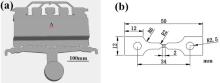
In this study, a specific casting, namely “ crash-box” (Fig. 1(a)) of 2.5 mm in wall thickness was produced under a TOYO BD-350V5 cold chamber die casting machine with AM60B magnesium alloy. The key processing parameters adopted during casting are given inTable 1. Two specimens were scanned and another two were tested in tension. All specimens were retrieved from location A in Fig. 1(a). The 3D morphology of the porosity was observed using the Phoenix vtome|xs (General Electric Company) with the voltage and current of 190 kV and 80 µ A, respectively. The size of specimen for the scanning was 50 mm × 20 mm × 2.5 mm, and the resolution was 70 µ m. The 3D morphology of the porosity was reconstructed with the scanning slice images using VGStudio Max 2.0 software.
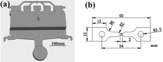 | Fig. 1. Configuration of (a) the “ crash box” casting, and (b) samples for in situ tensile deformation. Metallographic and porosity investigations were performed at location A. |
| Table 1 Processing parameters adopted during casting |
In situ tensile tests were carried out in the SEM chamber at a deformation speed of 0.1 mm/min. Configuration of the specimen is shown in Fig. 1(b). The metallographic preparation for the SEM and the in situ observation were performed according to the standard metallographic procedures [7]. The fracture surface and microstructure of the in situ tested specimens (of the shaded area shown in Fig. 1(b)) were examined using the Hitachi S-4500 SEM. All the metallographic samples were etched with a diluted acetic acid solution of 50 mL distilled water, 150 mL anhydrous ethyl alcohol and 1 mL glacial acetic acid.
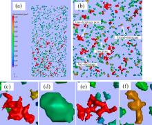
The 3D porosity morphology of HPDC AM60B alloy obtained via X-ray tomography is shown in Fig. 2. According to Fig. 2(a), the volume size of the porosity was mostly below 0.08 mm3. According to the formation mechanism and morphology (volume size and sphericity), four types of porosities, including gas-shrinkage pore, gas pore, net-shrinkage and island-shrinkage, could be identified, as shown in Fig. 2(b-f). Detailed information of the porosities in the two scanned specimens is shown in Table 2. After calculating the sphericity (i.e. the ratio between the surface area of a sphere and that of the porosity while keeping the same volume) of all porosities presented inside the sample, it was found that most (over 95%) of the gas pores and gas-shrinkage pores had a sphericity value of higher than 0.5, while it was relatively lower for net-shrinkage and island-shrinkage. In addition, comparing with gas-shrinkage pore and net-shrinkage, most (over 90%) of the gas pores and island-shrinkages had a much smaller volume, i.e. < 0.080 mm3. In this respect, the four types of porosities can be distinguished by its volume size and sphericity, detail of which is shown in Table 3.
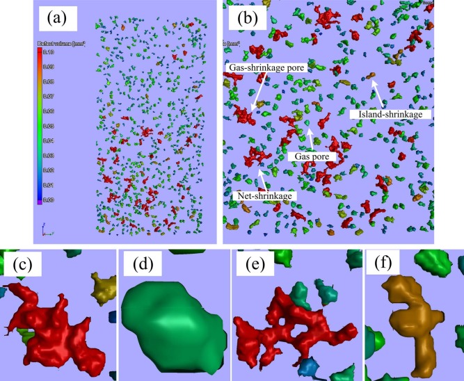 | Fig. 2. 3D morphology of porosity: (a) overall view of the porosities in specimen, (b) a zoom-in area showing the four types of porosities, such as (c) gas-shrinkage pore, (d) gas-pore, (e) net-shrinkage, and (f) island-shrinkage. |
| Table 2 Detailed information of the porosities in the two scanned specimens |
| Table 3 Comparison of the key characteristics of different porosities |
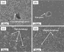
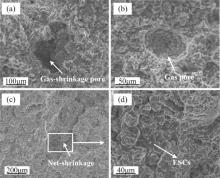
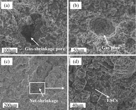
The porosities induced by gas entrapment could be classified into two types. One was gas-shrinkage pore, which was studied previously[9], and it was shown that because air in the gas pores was an efficient heat-insulating medium, the local solidification rate could be lowered and subsequently the shrinkage formed and usually connected to the gas pore, leading to the formation of gas-shrinkage pore. Thus, the gas-shrinkage pore was usually larger in size, and comprised of a round pore (gas pore) connected by irregular shrinkages (Fig. 3(a)). On the other hand, the individual gas pores (Fig. 3(b)), i.e. without connecting any shrinkage was smaller in size, and rounder in morphology. For the ESCs nucleated and grew up in shot sleeve, the ESCs, as a solid phase, would aggregate in the center of die cavity during the filling stage. During solidification, the contraction of the aggregated dendritic ESCs was difficult to be feed by melt for the dendrite interlocked with each other[28], leading to the formation of shrinkage pore. The shrinkage pores could also be classified into two types. One was net-shrinkage (Fig. 3(c)), usually formed by a cluster of interconnected micro-voids and always larger in size and more irregular in morphology at the condition of a large number of ESCs aggregated. The other one was called island-shrinkage (Fig. 3(d)), which comprised one or two micro-voids and was always smaller in size and less irregular in morphology at the condition of a few ESCs aggregated.
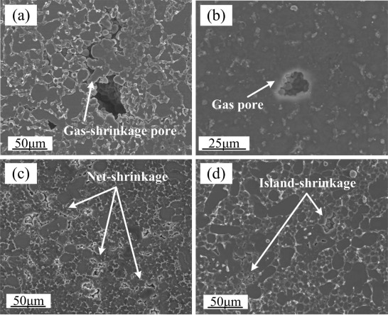 | Fig. 3. 2D morphology of (a) gas-shrinkage pore, (b) gas pore, (c) net-shrinkage, and (d) island-shrinkage. |
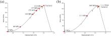
The stress-displacement curves of the two tensile test specimens at room temperature are shown in Fig. 4. The stresses at which the test was paused for SEM observation are labeled as dots with the stress values. In Fig. 4(a), six positions were chosen to observe the change of gas-shrinkage pore and net-shrinkage at different tensile stages. While inFig. 4(b), three positions were chosen to observe the change of gas pore and island-shrinkage at different tensile stages.
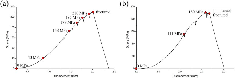 | Fig. 4. Stress-displacement curves of the two specimens during in-situ tensile tests. |
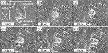
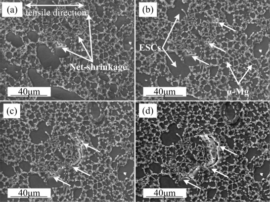
The change of one of the gas-shrinkage pores during tensile deformation is shown inFig. 5. The gas-shrinkage pore was surrounded by large dendritic ESCs (i.e. crystals solidified in the shot sleeve before entering the die cavity) and fine α -Mg grains which were solidified in die cavity. No significant change could be observed in the early stage of tensile deformation, as shown in Fig. 5(a) and (b), whereas, when the tensile stress exceeded about 148 MPa (see Fig. 5(c-f)), a clear crack initiated from the gas-shrinkage pore and grew rapidly along the ESC boundaries.
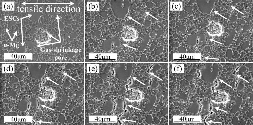 | Fig. 5. Change of the gas-shrinkage pore during the tensile deformation under different stress levels: (a) 0 MPa, (b) 40 MPa, (c) 148 MPa, (d) 179 MPa, (e) 197 MPa, and (f) 210 MPa. |
The change of two gas pores during tensile deformation is shown in Fig. 6. The gas pore inFig. 6(a) was surrounded by only fine α -Mg grains, while certain amount of ESCs were present around the gas pore in Fig. 6(d). It can be seen that the two gas pores hardly changed throughout the tensile deformation, although at later stage, cracks initiated at the ESC boundaries near the gas pores, as shown in Fig. 6(c) and (f).
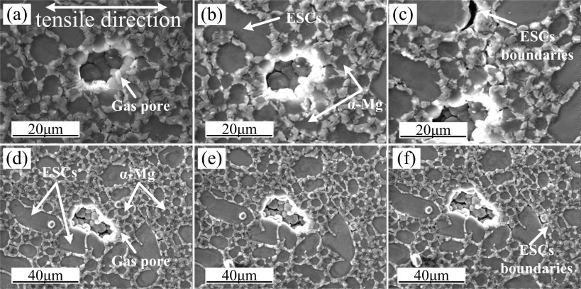 | Fig. 6. Change of two gas pores during tensile deformation. (a)-(c) show one gas pore while (d)-(f) show the other. The stress levels: (a) and (d) 0 MPa, (b) and (e) 111 MPa, and (c) and (f) 180 MPa, respectively. |
The change of one of the net-shrinkages during tensile deformation is shown in Fig. 7. The net-shrinkage in Fig. 7(a) comprised three micro-voids, as marked by the arrows. Further examination revealed that in 3D configuration, these micro-voids were interconnected with each other via shrinkage. Similar to the case of gas-shrinkage pore, no significant change could be observed on the net-shrinkage in the early stage of tensile deformation, as shown in Fig. 7(a) and (b). Whereas, when the tensile stress exceeded about 148 MPa, clear cracks were initiated from the net-shrinkage and grew rapidly along the grain boundaries, as shown in Fig. 7(c) and (d).
 | Fig. 7. Change of the net-shrinkage during tensile deformation under different stress levels: (a) 0 MPa, (b) 40 MPa, (c) 148 MPa, and (d) 210 MPa. |
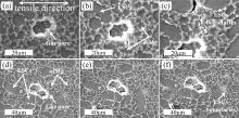
The change of two island-shrinkages during tensile deformation is shown in Fig. 8. One island-shrinkage, as shown in Fig. 8(a), was surrounded by only fine α -Mg grains, while the other was surrounded by a combination of ESCs and fine α -Mg grains, as shown inFig. 8(d). Similar as the gas pores, both island-shrinkages hardly changed throughout the tensile deformation, and cracks could only be observed nearby the island-shrinkage at the later stage of the tensile deformation.
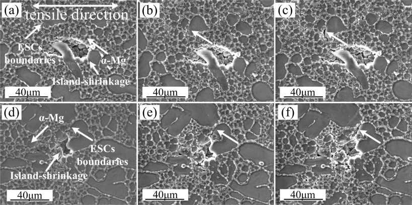 | Fig. 8. Change of two island-shrinkages during tensile deformation. (a)-(c) show one gas pore while (d)-(f) show the other. The stress levels: (a) and (d) 0 MPa, (b) and (e) 111 MPa, and (c) and (f) 180 MPa, respectively. |
According to Fig. 5, Fig. 6, Fig. 7 and Fig. 8, the gas-shrinkage pore and net-shrinkage, rather than the gas pore and island-shrinkage, were the potential sources for crack initiation. In addition, the presence of ESCs could increase the sensitivity for the generation of cracks during tensile deformation. According to Weiler et al.[14], the local areal fraction of porosity is the primary factor in determining the tensile properties (also the fracture position) of the magnesium alloy specimens, i.e. the specimens would fracture at the cross section with a minimum efficient force bearing area (largest areal fraction of porosity). Compared with the gas pore and island-shrinkage, the gas-shrinkage pore and net-shrinkage have a larger size and irregular morphology, and are always surrounded by a large number of dendritic ESCs. Thus, the gas-shrinkage pore and net-shrinkage always contribute to the cross section with a minimum efficient force bearing area, and have a relatively higher stress intensity factor. Because the crack always initiates at the location with high stress intensity factor, the gas-shrinkage pore and net-shrinkage are more sensitive to crack initiation under a stressed state, and the gas pore and island-shrinkage just reduce the efficient force bearing area.
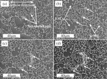
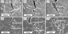
The propagation of a typical crack induced by the net-shrinkage in the specimen before fracture is shown in Fig. 9. Along the crack propagating direction, a number of porosities and secondary cracks[29] could be observed at the ESC boundaries (marked by arrows). Between porosities in the crack, the void opening displacement (VOD)[17] was larger in the location where ESCs existed, whereas in the location where only fine α -Mg grains were present, the VOD was smaller because the crack propagation could be effectively hindered by these fine microstructures.
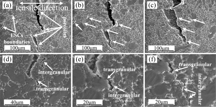 | Fig. 9. Crack propagation in specimen before fracture: (a-c) sequential stages of crack morphology with prolonged time, and (d-f) the front region of the crack propagation. |
Fig. 9(d-f) show the crack front where no porosities were present. It can be observed that the crack propagation was in a combination of trans-granular and inter-granular modes. The crack was initiated at shrinkage and propagated by connecting the nearby porosities along the direction roughly perpendicular to the tensile stress. Besides, the presence of the ESCs promoted the crack propagation, while the fine α -Mg grains hindered it.
For ESCs nucleated and grew up in shot sleeve, they would continue growing up in cavity simultaneously with the newly formed α -Mg grains when injected into the die cavity, thus, the metallurgical combination between large dendritic ESCs is smaller than that between fine α -Mg grains, i.e. the binding force between large dendritic ESCs is smaller than that between fine α -Mg grains. On the other hand, the binding force could be further reduced by the existence of porosities[9]. Accordingly, the crack would propagate in an inter-granular mode at locations where ESCs are present. At these locations without ESCs, a much finer microstructure would be formed because of the newly formed α -Mg grains, indicating a much stronger binding force. In this case, the crack would propagate along the direction roughly perpendicular to the tensile stress in a combination of trans-granular and inter-granular modes.
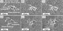
The morphology of a typical fracture after the tensile deformation is shown in Fig. 10. It can be seen that the fracture surface around either the gas-shrinkage pore (Fig. 10(a)) or net-shrinkage (Fig. 10(c)) was rough, but nearly flat around the gas pore (Fig. 10(b)). For the gas-shrinkage pore, comprised of a gas pore connected with irregular shrinkages surrounded ESCs (Fig. 3(a)), these irregular shrinkages would easily become the origin for crack initiation (Fig. 5(d)), and during further tensile deformation, the crack initiated at these shrinkages would propagate along the ESC boundaries in different directions (Fig. 5(f)) and a rough fracture surface was formed finally (Fig. 10(a)). Similar situation happened to the net-shrinkage, as shown in Fig. 10(c). On the other hand, because the gas pores had a rather spherical morphology (Fig. 3(b)) and were not the crack initiation source. The crack propagation was in a combination of transgranular and intergranular modes perpendicular to the tensile stress, leading to the fracture morphology around gas pore was nearly flat (Fig. 10(b)).
 | Fig. 10. Fracture morphology of (a) gas-shrinkage pore, (b) gas pore, (c) net-shrinkage and (d) zoom-in area of (c). |
In this study, the correlation between porosity and the fracture mechanism in HPDC AM60B alloy was investigated. Accordingly, the following conclusions can be drawn:
(1) Based on the formation mechanism and morphology characterization, the porosity in high pressure die casting of AM60B alloy can be classified into four types, such as gas-shrinkage pore, gas pore, net-shrinkage and island-shrinkage.
(2)Compared with gas pore and island-shrinkage, the gas-shrinkage pore and net-shrinkage were the dominant sources for crack initiation, and thus had a great deleterious effect on the mechanical properties of castings.
(3) During tensile deformation, the fracture occurred by interconnecting the porosities at the cross section with minimum efficient force bearing area. At these locations where ESCs were present, the crack would propagate along the ESC boundaries in an inter-granular mode, while at these locations without ESCs the crack would propagate roughly along the direction perpendicular to the tensile stress in a combination of trans-granular and inter-granular modes.
The authors thank the National Natural Science Foundation of China (No. 51275269), the Tsinghua University Initiative Scientific Research Program (No. 20121087918), and the National Science and Technology Major Project of the Ministry of Science and Technology of the People's Republic of China (No. 2012ZX04012011) for financial support.
The authors have declared that no competing interests exist.
| [1] |
|
| [2] |
|
| [3] |
|
| [4] |
|
| [5] |
|
| [6] |
|
| [7] |
|
| [8] |
|
| [9] |
|
| [10] |
|
| [11] |
|
| [12] |
|
| [13] |
|
| [14] |
|
| [15] |
|
| [16] |
|
| [17] |
|
| [18] |
|
| [19] |
|
| [20] |
|
| [21] |
|
| [22] |
|
| [23] |
|
| [24] |
|
| [25] |
|
| [26] |
|
| [27] |
|
| [28] |
|
| [29] |
|