
A Simple Method to Synthesize Multi-branched Carbon Fibers Using Cupric Chloride Aqueous Solution as Catalyst Precursor
[Qiuxiang Wang1 , Qian Zhang1 , Liping Chen2 , Liyan Yu1 , Lifeng Dong1, 3, *  ]
]
]
|
|


Carbon fibers with multi-branched structures were synthesized by chemical vapor deposition method using cupric chloride as catalyst precursor and acetylene as carbon source at different reaction temperatures. Effects of water vapor and reaction temperature on the growth mode of carbon fibers were investigated. Experimental results demonstrate that initial reaction conditions and temperature are key factors for the formation of different carbon materials. Carbon fibers with typical multi-branched structures can be obtained at 450 °C when cupric chloride solution was used as catalyst precursor. X-ray diffraction, field emission scanning electron microscopy, and transmission electron microscopy are used to characterize carbon materials, and the growth mechanisms of multi-branched carbon fibers were discussed.
Carbon materials, including carbon nanofibers[ 1] and carbon nanotubes[ 2], possess unique physical and chemical properties, such as high electrical conductivity[ 3],[ 4], high surface area[ 3], [ 5],[ 6], superb catalyst support[ 5], [ 6], [ 7],[ 8], and excellent hydrogen adsorption[ 9],[ 10], which have laid a solid foundation for future broad applications. Generally, these carbon materials can be obtained by chemical vapor deposition (CVD) method. During this synthesis process, hydrocarbon gas (i.e., acetylene, ethylene, and methane) and transition metal particles (i.e., Fe, Co, Ni, and their alloys) are used as carbon source and catalyst, respectively. Unlike ordinary carbon nanofibers or nanotubes, carbon materials with specific morphologies[ 11], [ 12],[ 13] (i.e., multi-branched carbon fibers and carbon nanocoils) have more advantages for their unique properties.
Different methods have been explored to synthesize carbon materials with specific morphologies. For instance, Zhao et al.[ 14] employed carbon fibers as substrates to fabricate aligned multi-walled carbon nanotubes by floating catalyst CVD method. Guo[ 15] reported that macroscopic multi-branched carbon trees could be obtained through the aggregation of iron-encapsulated carbon micro-spheres. Shi et al.[ 16] utilized an improved floating catalytic method to synthesize branched carbon fibers on the aggregated cores of Fe-SiO2 composites. Although great efforts have been made on controlling the morphology of carbon structures, a number of problems need to be solved, especially obtaining catalyst particles with defined morphology and dimension.
Catalyst powder is usually used as catalyst precursor for the CVD growth of carbon structures[ 11], [ 12], [ 13],[ 17], and the introduction of water vapor can be used to affect the growth process. For example, Hata et al.[ 17] found that water can stimulate the activity of catalyst particles and elongate their lifetime; Lee et al.[ 18] reported the effects of water on the yield of carbon nanotubes; and Amama et al.[ 19] demonstrated the interactions between water and catalyst particles. All the studies above indicate that water can play a critically important role in the growth of carbon materials.
In this study, we synthesized carbon fibers with multi-branched structures using cupric chloride aqueous solution as a catalyst precursor at 450 °C. Effects of water vapor (H2O) and reaction temperature on the growth of carbon fibers were investigated, and the growth mechanism of multi-branched carbon fibers was discussed.
A catalytic CVD method was employed to synthesize carbon fibers in a quartz tube (8 cm in diameter and 100 cm in length). At first, cupric chloride (CuCl2·2H2O, ≥99.999%) or its aqueous solution (3 mol/L) as a catalyst precursor was put into a ceramic boat, which was placed at the center of the reaction tube. Then the ambient pressure inside the tube was maintained in a low vacuum environment of 0.133 Pa (10 mTorr) before the carbon source acetylene was introduced at 200 °C. Reaction temperature was set as 300, 350, 400 or 450 °C for 20 min. The conditions of catalyst precursor were investigated at 200 °C in a vacuum environment and at 300 °C after the introduction of acetylene for 10 min. To further verify effects of water, carbon fibers were fabricated with the introduction of water vapor at 450 °C.
The morphology and structures of as-synthesized carbon materials and catalyst precursors were examined by field emission scanning electron microscopy (FESEM, JSM-6700F, JEOL) and transmission electron microscopy (TEM, JEM-2100, JEOL). Crystal structure of carbon materials was characterized by X-ray powder diffraction patterns (XRD, D-max-γA, Rigaku) with Cu Kα irradiation ( λ = 0.154178 nm).
During a CVD process, catalyst plays a critical role in the decomposition of hydrocarbon gas and the formation of carbon materials. The growth mode and morphology of carbon fibers correlate with physical and chemical characteristics of catalyst particles. The state of catalyst particles can also be altered by changing reaction atmosphere and reaction temperatures, and subsequently different kinds of carbon materials can be obtained[ 20],[ 21].
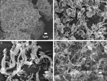
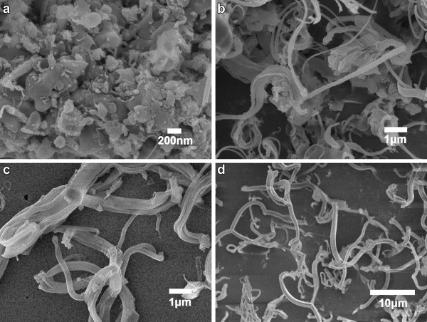
Reaction temperature is one of the most important parameters in a CVD process[ 20]. A higher temperature can provide more energy for the catalyst to decompose hydrocarbon gas, such as acetylene. In this study, cupric chloride was grinded prior to the CVD synthesis to enhance its catalysis activity. Fig. 1(a-d) displays FESEM images of carbon products using cupric chloride powder as a catalyst precursor at different reaction temperatures: 300, 350, 400, and 450 °C, respectively. Cupric chloride exhibits low catalytic activity at 300 °C since only small carbon pieces formed on the surface of catalyst particles (Fig. 1(a)). While the reaction temperature was increased to 350, 400 and 450 °C, carbon fibers were obtained (Fig. 1(b-d)). With the increase in reaction temperature, the morphology of carbon structures was changed from mixture of carbon pieces and fibers (Fig. 1(b)) to fibers (Fig. 1(d)). It is obvious that large catalyst particles produce pieces and small catalyst particles lead to fibers. This suggests that the conditions of catalysts can directly affect the growth of carbon structures.
 | Fig. 1. FESEM images of as-prepared carbon materials using cupric chloride powder as catalyst precursor at different reaction temperatures: (a) 300 °C; (b) 350 °C; (c) 400 °C; (d) 450 °C. |
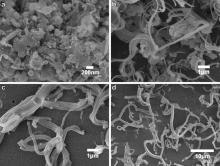
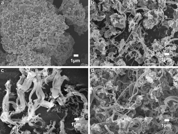
On the other hand, cupric chloride aqueous solution (3.0 mol/L) was used as catalyst precursor to synthesize carbon fibers, the aim of which is to alter initial reaction conditions for changing the growth mode of carbon materials[ 22]. As shown in Fig. 2, similar to powder catalysts, no carbon materials with typical fiber morphology were obtained at the reaction temperature of 300 °C. When the reaction temperature was increased to 350 and 400 °C, carbon fibers and multi-branched carbon fibers were obtained, respectively. At the reaction temperature of 450 °C, the proportion of branched carbon fibers was circa 35%. Most of the fibers had three or four branches formed on the surface of catalyst particles, which are commonly called as Y-shaped and X-shaped carbon fibers.
 | Fig. 2. FESEM images of as-prepared carbon materials using cupric chloride aqueous solution as catalyst precursor at different reaction temperatures: (a) 300 °C; (b) 350 °C; (c) 400 °C; (d) 450 °C. |
The most obvious difference appeared at 450 °C for the two kinds of carbon materials obtained using cupric chloride powder and aqueous solution. Only straight and coiled carbon fibers were synthesized using cupric chloride powder as precursor, and no multi-branched carbon fibers were observed. While cupric chloride aqueous solution was used, large amount of carbon fibers with multi-branched structures were obtained, and the branches formed on a catalyst particle had similar diameter, length, and surface smoothness.
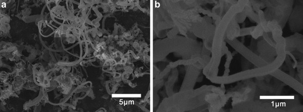
TEM characterizations were further conducted to investigate the obvious distinction among carbon fibers synthesized at different temperatures. For example, at the reaction temperature of 350 °C, a faceted catalyst particle exists inside carbon material, consisting of several fibers (Fig. 3(a and b)). The fibers seem to form at the vertices instead of the planes of the particles, suggesting that the atoms at the vertices are more active at assisting the fiber growth than those at the plane. While at 450 °C, carbon fibers formed on the planes of a catalyst instead of the vertices (Fig. 3(c and d)). Both SEM and TEM characterizations above indicate that the diameter, length, and morphology of multi-branched carbon fibers can be tailored with the change of reaction temperature. A high reaction temperature affiliates the crystallization of catalyst particles with well-defined facets for the synthesis of multi-branched fibers with smooth surface. This means that reaction temperature has an obvious effect on the characteristics of catalyst particles, including particle size and particle regularity, and subsequently affects the property of carbon materials, such as morphology and surface smoothness.
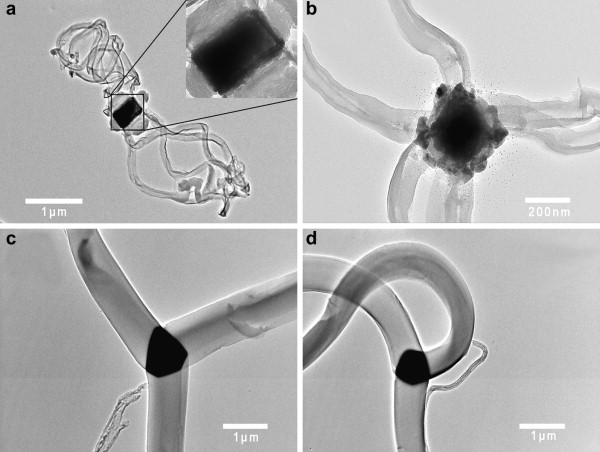 | Fig. 3. TEM images of multi-branched carbon fibers using cupric chloride aqueous solution as catalyst precursor at 350 °C (a and b) and 450 °C (c and d). |
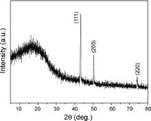
The XRD pattern of branched carbon fibers is shown in Fig. 4. The broad diffraction peak at around 20° results from carbon fibers, and three other distinctive diffraction peaks match well with standard copper diffraction patterns (PDF file No. 65-9026). No diffraction peaks of other metallic impurity or copper oxide were detected. Qin et al.[ 23] reported that this kind of amorphous carbon materials was a mixture of solid polymers from acetylene coupling and carbon from acetylene decomposition, the products obtained at 300 °C had a C/H atomic ratio of 1.11, and their hydrogen content, weight loss, and weight loss rate decreased with increasing reaction temperatures.
 | Fig. 4. XRD pattern of multi-branched carbon fibers obtained at 450 °C. |
Initial reaction conditions can decide the growth mode of carbon materials during a CVD process[ 22]. For instance, He et al.[ 24] reported that aqueous Ni-based mixtures can provide faster growth rate. Hansen et al.[ 25] stated that Cu crystals were transformed into spherical morphology due to the introduction of water. The adsorption of water on different exposed facets of Cu crystals can induce surface reconstructions and result in the reshaping of the Cu crystals. In this study, in comparison to cupric chloride powder, the aqueous solution of cupric chloride contributes to the formation of multi-branched carbon fibers. In order to reveal the role of water during the CVD growth, some experiments were conducted to investigate the status of catalyst precursors at 200 °C prior to the introduction of acetylene and at 300 °C after the introduction of acetylene for 10 min.
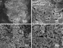
Prior to the introduction of acetylene at 200 °C, catalyst precursors have a dimension of several tens of microns (Fig. 5(a)). While after the introduction of acetylene for 10 min, catalyst particles become smaller with a size of several microns (Fig. 5(c)). This indicates that acetylene molecules interact with catalyst particles and consequently break them into small particles at a higher temperature 300 °C.
 | Fig. 5. FESEM images of catalyst precursors prepared at 200 °C without the introduction of acetylene (a and b) and at 300 °C after the introduction of acetylene for 10 min (c and d). |
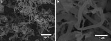
On the other hand, a mixture of water vapor and acetylene was used for the growth of carbon fibers at 450 °C instead of pure acetylene in order to study effects of water vapor on the fiber growth. As shown in Fig. 1(d), Fig. 6(a and b), there are no obvious differences in the morphology of carbon fibers due to the introduction of water vapor during the fiber growth process. Experimental results above indicate that the use of cupric chloride solution is a key factor for the growth of multi-branched fibers instead of water vapor as reported in the literature.
 | Fig. 6. FESEM images with different magnification of as-prepared carbon fibers obtained at 450 °C with the introduction of water vapor during the CVD process. |
In this paper, multi-branched carbon fibers were synthesized by a CVD method using cupric chloride solution as catalyst precursor at 450 °C. Effects of water vapor and reaction temperature on the growth mode of carbon materials were investigated. With increasing reaction temperature, high yield of multi-branched carbon fibers with small diameters were obtained. The aqueous solution of cupric chloride greatly assisted the formation of multi-branched carbon fibers, but the cupric chloride powder could not demonstrate similar effects even with the introduction of water vapor during the CVD process.
Acknowledgments
This work was partially supported by the Taishan Scholar Overseas Distinguished Professorship Program from the Shandong Province Government, the National Natural Science Foundation of China (Nos. 51172113 and 50872059), the Shandong Natural Science Foundation for Distinguished Young Scholars (No. JQ201118), the Shandong Natural Science Foundation (Nos. ZR2012EMM006 and ZR2011EMM005), the Qingdao Municipal Science and Technology Commission (No. 12-1-4-136-hz), and the Sabbatical Leave Award from Missouri State University.
| 1. |
|
| 2. |
|
| 3. |
|
| 4. |
|
| 5. |
|
| 6. |
|
| 7. |
|
| 8. |
|
| 9. |
|
| 10. |
|
| 11. |
|
| 12. |
|
| 13. |
|
| 14. |
|
| 15. |
|
| 16. |
|
| 17. |
|
| 18. |
|
| 19. |
|
| 20. |
|
| 21. |
|
| 22. |
|
| 23. |
|
| 24. |
|
| 25. |
|