


 λ¯ (nm)
Optical Spectra and Gain Properties of Ho3+/Pr3+ Co-doped LiYF4 Crystal
[Jiangtao Peng1 , Haiping Xia1, *  , Peiyuan Wang
1 , Haoyang Hu1 , Lei Tang1 , Yuepin Zhang1 , Haochuan Jiang2 , Baojiu Chen3 ]
, Peiyuan Wang|
|

 , Peiyuan Wang
The LiYF4 single crystals singly doped Ho3+ and co-doped Ho3+, Pr3+ ions were grown by a modified Bridgman method. The Judd-Ofelt strength parameters (Ω2, Ω4, Ω6) of Ho3+ were calculated according to the absorption spectra and the Judd-Ofelt theory, by which the radiative transition probabilities (
In the recent years, infrared solid state lasers, fiber lasers, and optical amplifiers have attracted much attention due to their wide applications in telecommunications, sensors, medicine, atmosphere transmission, optical parametric oscillators, electronic vibronic lasers, and broadband communication[ 1], [ 2],[ 3]. Ho3+ ion is one of the most important active ions applied to luminescence lasers because of its favorable energy level structure. It has been demonstrated that infrared laser emission of Ho3+ ion acts in the range of 1.2-4.9 μm including mid-infrared emission with transition5 I7 →5 I8 (2.0 μm) and5 I6 →5 I7 (2.9 μm) which attracted much attention in recent years[ 4],[ 5]. Previous investigations about 2.0 μm emission band were mainly focused on the spectroscopic properties of Ho3+-doped glasses, and on the analyzing the population inversion level of those materials from the gain cross section spectra which were calculated by absorption and emission cross section and ion concentrations[ 6],[ 7]. In order to achieve intense 2.9 μm mid-infrared emission for practical laser operation, co-doping of Pr3+ with Ho3+ has been used as a feasible alternative to quench efficiently the Ho3+:5 I7 level[ 8]. There are some reports about 2.9 μm emission of Ho3+-doped solid state materials[ 9],[ 10], but the optical gain properties at 2.9 μm emission, which is very important for laser operation to evaluate the performance of a laser media, have been rarely investigated.
Compared with fluoride glasses as host materials, the fluoride crystal LiYF4 has been proved as a suitable laser materials from ultra-violet to mid-infrared wavelength because of their many advantages with low phonon energy, low thermal lens effect and laser threshold, and high incorporation of trivalent rare-earth ions that substitute for the Y3+ ions[ 11],[ 12]. To our knowledge, Ho3+, Pr3+ co-doped LiYF4 crystal has not been successfully obtained due to the difficulties of crystal growth, and the optical properties of Ho3+, Pr3+ co-doped LiYF4 crystals around 2.9 μm have not been reported.
In this work, Ho3+-doped and Ho3+/Pr3+ co-doped LiYF4 crystals were successfully prepared. Enhanced emission at 2.9 μm is realized in Ho3+/Pr3+ co-doped LiYF4 crystal. The absorption and emission were measured, the spectroscopic investigations of 2.0 and 2.9 μm emission were carried out, and optical gain properties were analyzed.
Ho3+ singly doped and Ho3+/Pr3+ co-doped LiYF4 crystals were grown by Bridgman method in a resistively heated Bridgman furnace along <001> direction. The LiF, YF3, HoF3, PrF3 powders with 99.99% purity have been used as starting materials with the following molar compositions: 51.5%LiF-47.5%YF3-1%HoF3 and 51.5%LiF-47%YF3-1%HoF3-0.5%PrF3 (mol%), respectively. Details of the growth procedure were described in literature[ 11],[ 12]. The Ho3+ and Pr3+ concentrations in crystals were measured by an inductively coupled plasma (ICP) atomic emission spectrometry analysis. The Ho3+ and Pr3+ molar concentrations are 1.02% and 0.22% in Ho3+/Pr3+ co-doped LiYF4 crystals, and 1.02% in Ho3+ singly doped crystal. According to the measured density of crystals, the number density was calculated to be 3.011 × 1020 cm-3 for Ho3+ and 0.65 × 1020 cm-3 for Pr3+ in Ho3+/Pr3+ co-doped LiYF4 crystals, and 3.024 × 1020 cm-3 in Ho3+ singly doped crystal. The samples for spectroscopic measurements were cut from the grown LiYF4 crystals along <001> direction and polished to 2.20 mm thickness. Structures of Ho3+/Pr3+ co-doped LiYF4 crystal was investigated by X-ray diffraction (XRD) by using a XD-98X diffractometer (XD-3, Beijing) with Cu Kα radiation at 0.15403 nm, and the scanning 2 θ was from 10° to 90° with 0.02° increments and 6 s swept time. The absorption spectra in the range of 200-2500 nm of samples were carried out by using a U-4100 spectrophotometer. The emission spectra were tested with a Traix 320 type spectrometer (Jobin-Yvon Co., France) in the range of 1000-18,000 nm, and 1800-3020 nm excited by 640 nm light. All measurements were carried out at room temperature.
Fig. 1(a) presents the X-ray diffraction pattern for LiYF4 sample with 1.02 mol% Ho3+ and 0.22 mol% Pr3+. Meanwhile, the peak positions in JCPD 77-0816 of LiYF4 single crystal are listed in Fig. 1(b). It can confirm that Fig. 1(a) closely matches Fig. 1(b) and the current doping level do not cause obvious peak shift. The absorption spectra of the Ho3+-doped and Ho3+/Pr3+ co-doped LiYF4 crystals are shown in Fig. 2. There are nine absorption bands located at 358, 416, 448, 472, 482, 536, 638, 1150 and 1932 nm in Ho3+-doped LiYF4 crystals. They are ascribed to the transitions from the ground state5 I8 to the different excited states:3 H6,3 G5,5 G6 +5 F1,5 F2 +3 K8,5 F3,5 F4 +5 S2,5 F5,5 I6,5 I7 of Ho3+ ions, respectively. Four new bands at 2300, 1530, 1443 and 592 nm, which are corresponding to the ground state3 H4 to3 H6,3 F3,3 F4 and1 D2 of Pr3+ ion, appear in Ho3+/Pr3+ co-doped LiYF4 crystals besides above nine absorption bands of Ho3+ singly doped sample. A strong overlap around 2.0 μm between the5 I8 →5 I7 absorption transition of Ho3+ and the3H4 →3F2 absorption transition of Pr3+ is clearly shown in Fig. 2. It is expected that efficient energy transfer will occur from the5 I7 excited state of Ho3+ to the3 F2 states of Pr3+.
 | Fig. 1. (a) XRD pattern of the LiYF4:Ho3+/Pr3+; (b) standard line pattern of the orthorhombic phase LiYF4 (JCPD 77-0816). |
 | Fig. 2. Absorption spectra of Ho3+-doped and Ho3+/Pr3+ co-doped LiYF4 crystals. |
According to the framework of Judd-Ofelt theory[ 13],[ 14], the experimental oscillator strength fexp for a transition can be determined by using the absorption spectral data and the following formula:
 | (1) |
where N is the concentration of Ho3+, m and e are the mass and charge of electron, c is the velocity of light in vacuum, α( λ) = ln10·OD( λ) /d is absorption coefficient, d represents the thickness of the samples, OD( λ) is optical density, which is affected by the thickness of the samples, λ is the wavelength of the transition, Γ is the integrated absorbance for each absorption band used in calculation.
For the transitions from the ground state J to the excited states J′, the calculated oscillator strength, including both electronic dipole (ed) and magnetic dipole (md) transition component can be expressed as:
 | (2) |
 | (3) |
where h is the Planck constant, and J is the total angular momentum quantum number ( J = 8 in Ho3+). The term |<[ S, L] J|| U( t)||[ S′, L′] J>|2 = U( t) (different with U( t)) is the square of the reduced matrix element of the unit tensor operators, and can be considered independent on the host materials. Its values used in this work were quoted from literature[ 15].
 | (4) |
According to the selection rules for magnetic dipole (md) transition in the lanthanides which are Δ L = Δ S = 0, Δ J = 0, ±1, Δ M = 0, ±1; only the5 I8 →5 I7 transition in all observed transitions includes a magnetic dipole component. The value of f′ was calculated by Carnall et al.[ 15]. The Lorentz local field correction for the refractivity of the medium is χed = ( n2 + 2)/9 n and χmd = n. n is the refractive index of the host at the mean frequency of the transition. The refractive index in LiYF4 as light wavelength has been measured previously in literature[ 16]. We fit the data to the Sellmeier formula n( λ) = A + Bλ2/( λ2 - C) + Dλ2/( λ2 - E) in order to determine the Sellmeier coefficients. The Sellmeier coefficients were found to be ( A = 1.1648, B = 0.2827, C = 0.0081, D = 0.1571, E = 115.7947). The root-mean-square deviation ( δrms) which represents the goodness of the fit between experimental and calculated line strength is defined as:
 | (5) |
where M is the number of absorption bands which are used in the calculation. The values of δrms are 0.17 × 10⁻⁶ for Ho3+:LiYF4, and 0.24 × 10⁻⁶ for Ho3+/Pr3+:LiYF4, respectively.
Table 1 shows mean wavelength, integrated absorbance, measured and calculated oscillator strength of the Ho3+-doped and Ho3+/Pr3+ co-doped LiYF4 at room temperature. From the least-square fit of measured and calculated electric dipole oscillator strength with Eq. (2), the three Judd-Ofelt intensity parameters of Ho3+ ions were obtained and shown in Table 2. The Ω2, Ω4, and Ω6 in Ho3+:LiYF4 are 2.45 × 10⁻²⁰ cm2, 1.01 × 10⁻²⁰ cm2, and 0.96 × 10⁻²⁰ cm2, respectively, and in Ho3+/Pr3+:LiYF4 are 1.51 × 10⁻²⁰ cm2, 1.96 × 10⁻²⁰ cm2, and 1.05 × 10⁻²⁰ cm2, respectively. The intensity parameters Ω2, Ω4, Ω6 and oscillator strength provide information on the symmetry and bonding of rare-earth polyhedra within the matrix[ 23]. Ω2 is strongly affected by covalency and Ω6 is closely related to the rigidity of the host environment. It can be noted from Table 2 that the Ω2 value decreases from 2.45 × 10⁻²⁰ to 1.52 × 10⁻²⁰ cm2 as Pr3+ ion introduction into Ho3+:LiYF4, indicating that the Pr3+ ion has an effect on the local environment of Ho3+.
| Table 1. Mean wavelength, integrated absorbance, measured and calculated oscillator strength of the Ho3+-doped and Ho3+/Pr3+ co-doped LiYF4 at room temperature |
| Table 2. Comparison of Judd-Ofelt parameters of Ho3+ ions in Ho3+-doped and Ho3+/Pr3+ co-doped LiYF4 and other crystals |
Using Judd-Ofelt intensity parameters Ω2,4,6, the radiative parameters, the radiative transition rates ( A), fluorescence branching ratios ( β), and radiative decay time ( τrad), can be obtained. The radiative decay rate including electronic and magnetic dipole transition from an excited manifold J to a lower manifold J′ can be therefore calculated by the equation:
 | (6) |
where Sed and Smd represent the electric and magnetic dipole line strength, respectively, and they are given by
equation(7)
 | (7) |
 | (8) |
The fluorescence branch ratio of a transition from an excited state J to the lower lever J′ is given by
 | (9) |
Then the radiative lifetime of an excited state J is associated with the radiative decay rate in the relationship of
 | (10) |
where the summation is over all transitions to every terminal state J.
The calculated radiative probabilities, radiative branching ratios and radiative lifetime of Ho3+-doped and Ho3+/Pr3+ co-doped LiYF4 are listed in Table 3.The calculated radiative lifetime ( τrad) of the listed excited state J′ in Ho3+/Pr3+:LiYF4 decreases by comparing with Ho3+:LiYF4. Clearly, the calculated radiative rates of Ho3+:5 I6 →5 I7 transition is higher in Ho3+/Pr3+:LiYF4, indicating that the 2.9 μm radiation tends to occur easily when Pr3+ is introduced.
| Table 3. Calculated radiative rates, branching ratios and radiative lifetime for Ho3+:LiYF4 crystals and Ho3+/Pr3+:LiYF4 crystals |
The emission cross section is a key parameter influencing the potential laser performance. Based on the measured absorption spectra shown in Fig. 2, the absorption and emission cross section for Ho3+ emissions at 2.05 μm are calculated by using Beer-Lambert equation and McCumber theory[ 24]. The emission cross sections σem can be calculated by the following expression:
 | (11) |
where σabs( λ) = α( λ)/ N represents the absorption cross sections, α( λ) is absorption coefficient and N is the number of ions in the unit volume, Zl and Zu are the partition functions of the lower and upper manifolds, respectively. Zl/ Zu can use the value of 0.8052 for the transitions5 I7 →5 I8 (2.05 μm) as reported in literature[ 19], and Ezl is the zero-line energy, and is defined as the energy difference between the lowest Stark level of the upper manifold and the lowest Stark level of the lower manifold. The energy levels reported for Ho3+:LiYF4 in literature[ 25] were used to calculate the zero-line energies for the manifolds studied. k is the Boltzmann's constant, T is the absolute temperature. The derived absorption and emission cross sections for 2.05 μm emissions are shown in Fig. 3. The maximum emission cross section of Ho3+:LiYF4 crystal around 2.05 μm is 0.51 × 10⁻²⁰ cm2. This value for 2.05 μm can be compared with one of some crystals: Ho3+:SrWO4 (1.05 × 10⁻²⁰ cm2)[ 21], Ho3+:SrMoO4 (0.271 × 10⁻²⁰ cm2)[ 22], Ho3+:LiYF4 (0.39 × 10⁻²⁰ cm2)[ 25], Ho3+:Y3Al5O12 (0.45 × 10⁻²⁰ cm2)[ 26]. By comparing the parameters all above, the Ho3+:LiYF4 crystal may be a good laser material for 2.0 μm infrared laser.
 | Fig. 3. Absorption and emission cross section line shapes for Ho3+ emissions at 2.05 μm in Ho3+:LiYF4 crystal. |
Based on the above absorption and emission cross section spectra, the optical gain coefficient g( λ) can be calculated by the following equation:
 | (12) |
where N1 and N2 represent the population volume-densities of upper and lower levers, respectively. The total population volume-density is N = N1 + N2, thus the gain cross section spectrum G( λ) can be given by:
 | (13) |
where population inversion P = N2/ N is assigned to the concentration ratio of Ho3+, and 0 ≤ P ≤ 1. The calculated gain cross sections for 2.05 μm transition of Ho3+ as a function of wavelength with different P values are shown in Fig. 4.It can be seen that the positive gain appears when P is around 0.3. It means that the pump threshold for obtaining 2.05 μm laser is probably lower, and this is an advantage for Ho3+-doped LiYF4 infrared lasers.
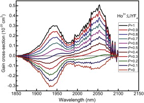 | Fig. 4. Gain cross-section spectra of Ho3+:5 I7 →5 I8 in Ho3+:LiYF4 crystal. |
Fig. 5(a) shows the infrared emissions spectra of Ho3+:LiYF4 and Ho3+/Pr3+:LiYF4 crystal from 1100 to 3000 nm under the 640 nm excitation. Emission bands at 1.2, 2.05, and 2.9 μm were observed.
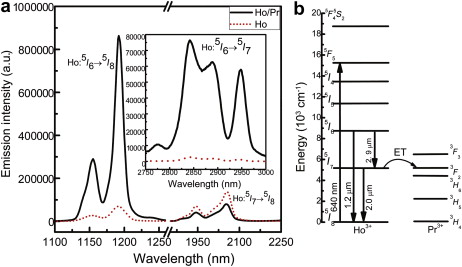 | Fig. 5. (a) Infrared emission spectra of Ho3+:LiYF4 and Ho3+/Pr3+:LiYF4 crystal around 1.2 μm together with 2.05 and 2.9 μm under excitation at 640 nm, inset is the spectra around 2.9 μm; (b) simplified energy level diagram for Ho3+/Pr3+:LiYF4 crystal when pumped at 640 nm. |
Under 640 nm excitation, in Ho3+/Pr3+ co-doped fluoride crystal, the intensity of three greatly enhanced mid-infrared emissions around 2841, 2888, and 2948 nm from the transition of Ho3+:5 I6 →5 I7 are quite strong which are shown in the inset of Fig. 5(a). But the intense emission intensity at 1.2 μm ascribed to the Ho3+:5 I6 →5 I8 transition was also observed, which is not beneficial to make the population inversion of the upper 2.9 μm laser level (Ho3+:5 I6), and the corresponding transition Ho3+:5 I6 →5 I8 (1.2 μm) is only observed in low phonon energy host, such as fluoride[ 19], chalcohalide[ 27],[ 28] and oxyfluoride[ 29] glasses and crystals. However, a significant reduction in the emission intensity of the5 I7 level at 2.0 μm is observed, which justifies that Pr3+ ions can be used effectively to depopulate the Ho3+:5 I7 level. The emission at 2.0 μm is broad, which usually originates from the transition Ho3+:5 I7 →5 I8, and has been observed in many types of host including glasses[ 27] and crystals[ 19],[ 30] and the peak wavelength depends on the host materials[ 31]. The simplified energy level diagram of the Ho3+, Pr3+ co-doped system is shown in Fig. 5(b). When the crystal is pumped by a 640 nm light, ions in5 F5 level decay nonradiatively to the5 I6 level, then decay radiatively to5 I7 level with 2.9 μm emission or nonradiatively to5 I7 level. Since the energy gap between the Pr3+:3 F2 and Ho3+:5 I7 level is very small, the energy of the Ho3+:5 I7 level will be transferred to the Pr3+:3 F2 level (ET shown in Fig. 5(b)), which depopulates the Ho3+:5 I7 level, and makes the possibility of the 2.9 μm emission. The emission cross sections for 2.9 μm mid-infrared transition in Ho3+/Pr3+:LiYF4 crystal are subsequently calculated by the Fuchtbauer-Ladenburg equation[ 32]:
 | (14) |
where Arad is radiative rate, I ( λ ) is the emission spectrum intensity, I(λ)/∫λI(λ)ⅆλI(λ)/∫λI(λ)ⅆλ is the normalized line shape function of the experimental emission spectrum, c is the speed of light, n is the refractive index. By using the emission spectra data, the emission cross section for transition Ho3+:5 I6 →5 I7 in Ho3+/Pr3+ co-doped and Ho3+ singly doped LiYF4 crystals were obtained and are shown in Fig. 6(a) and (b), respectively. Obviously, the maximum value of the emission cross section around 2950 nm, 0.68 × 10⁻²⁰ cm2, is larger than the value of 0.53 × 10⁻²⁰ cm2 in Ho3+ singly doped LiYF4 crystal calculated by the same method. When the emission cross section for the transition Ho3+:5 I6 →5 I7 at 2.9 μm is known, the absorption cross section σabs can be derived from the calculated σem by using the deformation of the Eq. (12):
 | (15) |
where Ezl is the zero-line energy defined as the energy gap between5 I6 and5 I7 manifolds, and the value is 3517 cm- 1 [ 19]. For the Ho3+:LiYF4, the value of Zu/ Zl is 0.98[ 24].
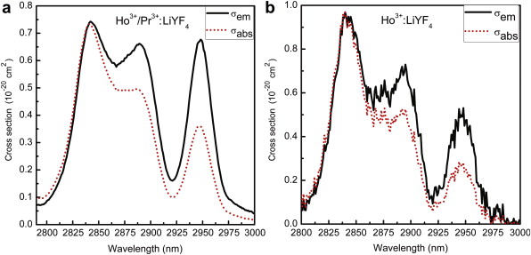 | Fig. 6. Emission and absorption cross sections for the transitions Ho3+:5 I6 →5 I7 in Ho3+/Pr3+:LiYF4 (a), and in Ho3+:LiYF4 (b) crystals. |
Based on the calculated absorption and emission cross-section spectra, the gain cross section G( λ) for 2.9 μm mid-infrared emission as a function of wavelength with different P values can be calculated according to the Eq. (13) and the spectra of the transition Ho3+:5 I6 →5 I7 in Ho3+/Pr3+:LiYF4 and Ho3+:LiYF4 crystal are shown in Fig. 7(a) and (b), respectively.
 | Fig. 7. Gain cross-section spectra of Ho3+:5 I6 →5 I7 in Ho3+/Pr3+:LiYF4 (a) and in Ho3+:LiYF4 (b) crystal. |
Evidently, while P varies from 0.0 to 1.0 with an increasing step of 0.1, the gain cross section becomes positive once the population inversion level reaches 40% in Ho3+/Pr3+:LiYF4 crystal, but in Ho3+ singly doped LiYF4 crystal, the gain cross section does not become positive until the population inversion level reaches 50%. Obviously, with the introduction of Pr3+ ions, a low pumping threshold is achieved for the Ho3+:5 I6 →5 I7 laser operation.
Ho3+:LiYF4 crystal and Ho3+/Pr3+:LiYF4 single crystals with good optical quality can be grown by Bridgman method. The Pr3+ ion has great effect on the intensity parameters, radiative transition probabilities, radiative lifetimes and the branching ratios of Ho3+/Pr3+:LiYF4, which result from the interaction between Ho3+ and Pr3+ ions. An enhanced mid-infrared emission at 2.9 μm as observed in Ho3+/Pr3+:LiYF4 crystal under excitation at 640 nm is due to the energy transfer from the Ho3+:5 I7 level to the Pr3+:3F2 level. The emission cross sections emission at 2.9 μm in Ho3+/Pr3+:LiYF4 crystal is 0.68 × 10⁻²⁰ cm2 which is larger than the value of 0.53 × 10⁻²⁰ cm2 in Ho3+ singly doped LiYF4 crystal. The gain cross section is more likely to become positive in Ho3+/Pr3+:LiYF4 than that in Ho3+ singly doped LiYF4 crystal. All the results show that the Ho3+/Pr3+:LiYF4 crystal may be a potential single crystal for 2.9 μm mid-infrared laser application.
Acknowledgments
This work was supported by the National Natural Science Foundation of China (Grant Nos. 51272109 and 50972061), the Natural Science Foundation of Zhejiang Province (Grant Nos. R4100364), the Natural Science Foundation of Ningbo City (Grant No. 2012A610115) and K.C. Wong Magna Fund in Ningbo University.
| 1. |
|
| 2. |
|
| 3. |
|
| 4. |
|
| 5. |
|
| 6. |
|
| 7. |
|
| 8. |
|
| 9. |
|
| 10. |
|
| 11. |
|
| 12. |
|
| 13. |
|
| 14. |
|
| 15. |
|
| 16. |
|
| 17. |
|
| 18. |
|
| 19. |
|
| 20. |
|
| 21. |
|
| 22. |
|
| 23. |
|
| 24. |
|
| 25. |
|
| 26. |
|
| 27. |
|
| 28. |
|
| 29. |
|
| 30. |
|
| 31. |
|
| 32. |
|