
A Facile Synthetic Approach to Reduced Graphene Oxide-Fe3O4 Composite as High Performance Anode for Lithium-ion Batteries
[Yanhong Chang1, 2, *  , Jing Li
1, 3 , Bin Wang3 , Hui Luo4 , Linjie Zhi3, ** ]
, Jing Li]
|
|


O4 (rGO-Fe3O4) composite has been prepared via a facile and effective hydrothermal method by synthesizing Fe3O4 nanospheres on the planes of reduced graphene oxide (rGO). Characterizations suggest the successful attachment of Fe3O4 nanospheres to rGO sheets. The rGO-Fe3O4 composite (66.7 wt% of Fe3O4 in the composite) exhibits a stable capacity of 668 mAh g-1 without noticeable fading for up to 200 cycles in the voltage range of 0.001-3.0 V, and the superior performance of rGO-Fe3O4 is clearly established by comparison of the results with those from bare Fe3O4 nanospheres (capacity declined to 117 mAh g-1 only at the 200th cycle). The excellent electrochemical performance of rGO-Fe3O4 composite can be attributed to the fact that the uniform dispersion of the Fe3O4 nanospheres growing on the rGO sheets avoids aggregation during Li uptake-release cycling, which is desired for cycle stability. Meanwhile, the rGO sheets afford not only elastic buffer to alleviate the volume variations of Fe3O4 nanospheres, but also good ionic and electronic transport medium in the electrode.
Developing devices and related materials for producing and storing electricity are key issues to meet the increasing energy demand. Rechargeable lithium-ion batteries (LIBs) are currently being explored for high-power energy applications in a wide range of both civil and military, such as electronic devices, electric vehicles and implantable medical devices[ 1], [ 2], [ 3]. Their energy density and power density mainly depend on the physical and chemical properties of both cathode and anode materials. Graphite is widely commercial anode material for LIBs, however, the theoretical specific capacity of graphite is only 372 mAh g-1. Resulting from the growing demand for high energy and power density, the attention has been shifted from graphitic anodes to electrochemically active metals and transition metal oxides, such as Si[ 4], Sn[ 5], Co3O4[ 6], Fe2O3[ 7], and Fe3O4[ 6], due to their high theoretical capacities and promising potential. Among them, Fe3O4 has been considered as one of the most prominent candidates for next generation LIBs anode materials for its higher specific capacity, eco-benignity and natural abundance[ 8], [ 9], [ 10]. Nevertheless, the Fe3O4 anode materials have poor cycle performance during the continuous charge/discharge cycling because of the severe aggregation and drastic volume change of Fe3O4 particles[ 8], [ 9], [ 10], [ 11], which reduces the surface area of active materials and leads to the breakdown of electrical connection between anode materials and current collectors, respectively. To alleviate these problems, nanostructured oxide/carbon hybrids, such as carbon nanotube composites[ 11], [ 12], carbon coated nanospindles[ 8]/nanorods[ 13]/nanocapsules[ 14] are being thought to conquer the challenge with good cyclic performance as well as to maintain high specific capacity. Among these approaches, carbon coating has been proved to effectively improve the cyclic performance, which serves as a buffer to relieve the volume change and preserve the electrode integrity[ 9], [ 15], [ 16].
Graphene, a single layer of sp2-bonded carbon atoms patterned in a hexagonal lattice, exhibits prominent thermal stability[ 17], superior electronic conductivity[ 18], remarkable structural flexibility[ 19], and high specific surface area[ 20]. These unique properties of graphene make it become an ideal material for many applications, including microelectronics, batteries, supercapacitors, sensors and mechanical resonators[ 21], [ 22], [ 23], [ 24], [ 25]. In LIBs, graphene-based composites have emerged as quite intriguing electrode materials[ 26], [ 27], [ 28], [ 29], [ 30]. Recently, the Fe3O4 particles combined with graphene have been reported and display several advantages[ 31], [ 32], [ 33], [ 34]. Firstly, ultrathin graphene sheets can prevent the aggregation of Fe3O4 particles[ 35], [ 36]. Secondly, the graphene can provide void space against the volume changes of the Fe3O4 particles during lithium-ion insertion/extraction process[ 37], which can improve the cycling performance. Finally, the Fe3O4 particles are anchored on the planes of graphene, which may lead to a high rate performance due to the high electronic conductivity of graphene sheets and short path length for Li+ transport of Fe3O4 particles[ 38]. However, the reported strategies for preparing graphene-Fe3O4 composite are complicated, involving additional reduction agents such as N2H4[ 39], NaBH4[ 40] and additional annealing steps[ 31].
Herein, we reported a facile one-pot hydrothermal route to prepare rGO-Fe3O4 composite combining Fe3O4 nanospheres with rGO sheets, directly from graphene oxide (GO) and iron chloride (FeCl3·6H2O) in the presence of ethylene glycol. The illustration of the synthesis process is shown in Scheme 1. Through this rapid and robust in situ approach, the reduction of GO and the deposition of Fe3O4 nanospheres on rGO sheets occurred simultaneously under alkaline condition by hydrolyzing of potassium acetate (KAc), and ethylene glycol (EG) served as both solvent and reducing agent. The resultant hybrid rGO-Fe3O4 composite materials were obtained by hydrothermal method without additional reducing agent or further annealing step. Characterizations showed that the Fe3O4 nanospheres were uniformly distributed on the rGO sheets. The electrochemical performance of rGO-Fe3O4 composite as anode electrode material for LIBs was investigated and compared with bare Fe3O4. The experimental results indicated that the rGO-Fe3O4 composite could indeed deliver a high reversible specific capacity together with excellent cycle performance.
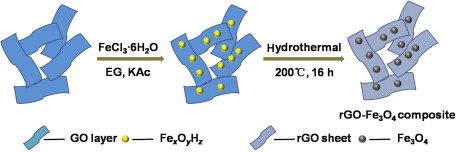
Scheme 1.Synthesis process of rGO-Fe3O4 composite.
Graphite powder was obtained from Tianjin Chemicals Company (China). Other reagents were purchased from Beijing Chemicals Company (China), all chemicals used in our experiments were reagent grade without further purification.
The morphology and structure of the samples were characterized by transmission electron microscopy (TEM, Tecnai G2 F20 U-TWIN), scanning electron microscopy (SEM, Hitachi S4800), polycrystalline X-ray diffraction (XRD, Rigaku-D/max 2005B2+/PCX), and X-ray photoelectron spectroscopy (XPS, PH1500C) under room temperature. Fourier transform infrared spectra (FTIR) were recorded on a Spectrum One FTIR spectrometer from 4000 to 400 cm-1. The thermal properties of the samples were recorded by a thermogravimeter (TGA/DSC, Netzsch-STA 449C) measured from room temperature to 1000 °C at a heating rate of 10 °C/min in air.
GO was synthesized from natural graphite powder by a modified Hummers method[ 41]. Then, aqueous suspension of GO at a concentration of 5 mg ml-1 was prepared. In a typical procedure[ 32], 50 ml of ethylene glycol was dropped into 10 ml GO suspension by dropper and the mixture was sonicated for 1 h, then 0.2 g of FeCl3·6H2O was homogeneously dissolved in the obtained light brown dispersion. Subsequently, 4.3 g of potassium acetate (KAc) and 1.0 g of polyethylene glycol were poured in the mixed solution, followed by stirring constantly for 1 h, and then the mixture was sealed in a Teflon-lined stainless steel autoclave at 200 °C for 16 h. After hydrothermal treatment, the autoclave was naturally cooled to room temperature, and the rGO-Fe3O4 composite was then obtained after centrifugation and washing with ethanol. The as-obtained sample was dried at 50 °C in a vacuum oven for 12 h. To prepare rGO and bare Fe3O4 nanospheres for comparison, the synthesis was carried out in the absence of FeCl3·6H2O or GO under the same other conditions as the preparation rGO-Fe3O4, respectively.
The electrochemical properties of the prepared rGO-Fe3O4 composite and bare Fe3O4 nanospheres as anode materials for LIBs were evaluated by galvanostatic charge-discharge technique at 25 °C. The test electrodes were prepared by mixing active material (80 wt%) with acetylene black (10 wt%) as a conductive agent and polyvinylidenedifluoride (10 wt%) dissolved in N-methyl-2-pyrrolidone (NMP) as a binder to form a slurry. The slurry was then coated onto a copper foil with 14 mm diameter. These electrodes were then pressed and dried under vacuum at 100 °C for 12 h. CR2032 coin-type cells were ultimately assembled in an argon-filled glovebox. The prepared rGO-Fe3O4 composite or bare Fe3O4 nanospheres was used as test electrode, metallic lithium as the counter/reference electrode, 1 mol/l LiPF6 dissolved in a mixture of ethylene carbonate (EC), diethyl carbonate (DEC) (1:1 by volume) as the electrolyte, and polypropylene film as a separator. The charge/discharge measurements were carried out by using the land battery program-control test system (CT2001A) at a constant current density of 100 mA g-1 over a voltage range of 0.001-3.0 V vs Li/Li+.
Fig. 1(a) shows the typical SEM image of rGO-Fe3O4 composite, which exhibits that the Fe3O4 nanospheres with a few aggregations are dispersed on the basal planes of rGO sheets. This appropriate connection between Fe3O4 and rGO enhances electrode stability against cycling processes for lithium storage. In a magnified SEM image of composite (Fig. 1(b)), both the fringe of rGO sheets and the morphology of Fe3O4 nanospheres can be observed, and the diameter of most of the nanospheres is slightly different ranging from 100 to 200 nm. The TEM images (Fig. 1(c and d)) of the composite reveal morphology features which are in agreement with the SEM result. From the TEM image at a higher magnification (Fig. 1(d)), it clearly shows the lattice fringes of Fe3O4 with a spacing of 0.48 nm, which agrees well with the d-spacing of the (111) plane of Fe3O4.
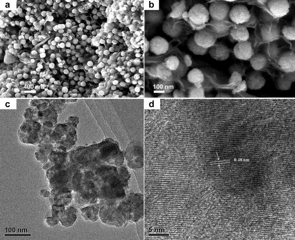 | Fig. 1. (a) SEM image of rGO-Fe3O4 composite, (b) high magnification SEM image of rGO-Fe3O4 composite, (c) TEM image of rGO-Fe3O4 composite, (d) high magnification TEM image of rGO-Fe3O4 composite. |
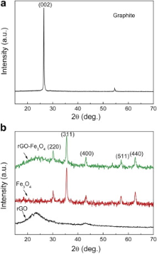
Typical XRD patterns of the natural graphite, as-prepared rGO-Fe3O4 composite, rGO, and Fe3O4 nanospheres are presented in Fig. 2. As displayed in Fig. 2(a), the original graphite shows the sharp characteristic (002) diffraction peak at around 2 θ = 26.5°. After oxidation treatment ( Fig. 2(b)), the rGO-Fe3O4 composite and rGO possess the weaker, broader diffraction peak of (002) than pristine graphite because of the introduction of oxygen-containing functional groups on the graphite sheets. These results suggest that more disordered stacking rGO sheets are presented in the rGO-Fe3O4 composite[ 16]. All of the other diffraction peaks can be indexed as the face-centered cubic structured Fe3O4 nanospheres that coincide well with the standard data of Fe3O4 (JCPDS card 19-0629), which indicates that the rGO-Fe3O4 composite consists of disorderedly stacked rGO sheets and well crystallized Fe3O4.
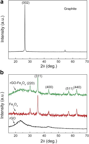 | Fig. 2. XRD patterns of: (a) natural graphite, (b) rGO, Fe3O4 nanospheres, and rGO-Fe3O4 composite. |
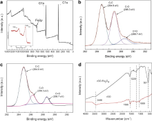
To determine the chemical composition of rGO-Fe3O4 composite, XPS measurement was carried out (Fig. 3(a)). The broad peaks around 710.9 and 724.5 eV are typical for the Fe2 p, corresponding to the Fe2 p3/2 and Fe2 p1/2 spin orbit peaks of Fe3O4, respectively (as shown in the inset of Fig. 3(a)), implying the formation of a mixed oxide of Fe(II) and Fe(III). In Fig. 3(b), the C1 s XPS spectrum of GO contains three components: the non-oxygenated ring C-C (284.8 eV), C-O species (286.3 eV) and C=O species (288.7 eV)[ 26]. After the hydrothermal reduction ( Fig. 3(c)), the intensity of oxygenated peaks is significantly less than that of non-oxygenated peaks, and the remarkable decrease of oxygenated functional groups indicates the deoxygenation of GO during the reaction process. FTIR spectra of rGO and rGO-Fe3O4 composite are shown in Fig. 3(d). For rGO, the broad and intense band at 3446 cm-1 and the peak at near 1580 cm-1 are possibly attributed to the vibrations of O-H and C=C groups on the rGO sheets. Peaks located at 1069 and 1228 cm-1 are most often related to stretching vibrations of C-O groups. For rGO-Fe3O4 composite, the band at 581 cm-1 was the characteristic stretching vibrations of Fe-O[ 39]. The FTIR results further testified the reduction reaction in the hydrothermal process, and the FTIR spectrum of the rGO-Fe3O4 composite became a combination of the absorption bands of rGO and Fe3O4 after mixing the two components.
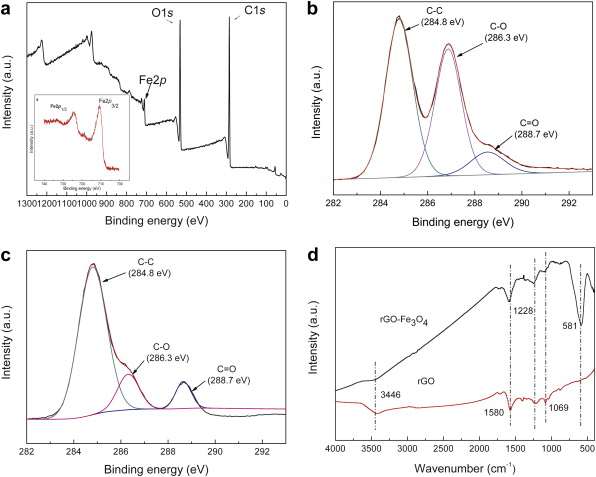 | Fig. 3. (a) XPS spectra of rGO-Fe3O4 composite, the inset is the high-resolution spectra of Fe2 p, (b) C1 s XPS spectra of GO, (c) C1 s XPS spectra of rGO-Fe3O4 composite, (d) FTIR spectra of rGO and rGO-Fe3O4 composite. |
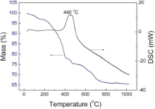
For quantifying the amount of rGO and Fe3O4 in the rGO-Fe3O4 composite, TGA was carried out in air from room temperature to 1000 °C at a rate of 10 °C/min. As can be seen from Fig. 4, there are three weight loss processes. A slight weight loss below 140 °C is attributed to the evaporation of the adsorbed moisture or gas molecules. Then the rGO-Fe3O4 composite experiences abrupt weight loss between 140 and 400 °C, which can be assigned to the destruction of labile oxygen-containing functional groups. The TGA/DSC curves of rGO-Fe3O4 composite present a characteristic step/peak in the range from 400 to 800 °C. Correspondingly, the DSC curve shows a strong exothermal peak centered at 440 °C. It can be assigned to the decomposition of rGO nanosheets[ 36]. When the temperature reaches 800 °C, the weight of the sample remains and almost no weight loss occurs after this temperature. Therefore, the mass retained directly translates into the amount of Fe3O4 in the composite. By using this method, it was estimated that the amount of Fe3O4 in rGO-Fe3O4 composite was about 66.7 wt%.
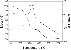 | Fig. 4. TGA and DSC curves of rGO-Fe3O4 composite in air atmosphere. |
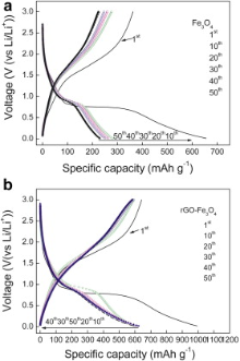
The electrochemical performance of rGO-Fe3O4 composite as anode was examined through galvanostatic charge/discharge cycling at 100 mA g-1, for comparison, anodic property of bare Fe3O4 nanospheres was also tested under the same conditions (Fig. 5(a and b)). In the first discharge step, both rGO-Fe3O4 and bare Fe3O4 present an extended/long voltage plateau at about 0.70 V, followed by a sloping curve down to the cutoff voltage of 0.001 V, indicating a typical character for transition metal oxide anodes[ 30]. It can be seen that the first discharge and charge capacities are 992.9 and 642 mAh g-1 for rGO-Fe3O4 composite (the Coulombic efficiency is 65%), 655.6 and 362.6 mAh g-1 for bare Fe3O4 (the Coulombic efficiency is 55%), respectively. Compared with the bare Fe3O4, the extra capacity of the rGO-Fe3O4 composite may be ascribed to the larger electrochemical active surface area of rGO sheets and grain boundary area of the Fe3O4 nanospheres[ 16]. Large irreversible capacity observed in the first cycle may be caused by the formation of solid electrolyte interphase (SEI) and the reaction of the lithium-ion with oxygen-containing functional groups remaining unreduced on the surface of rGO sheets[ 35].
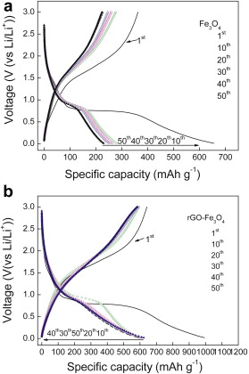 | Fig. 5. Charge/discharge profiles of: (a) Fe3O4, (b) rGO-Fe3O4 composite. |
After ten charge/discharge cycles, the rGO-Fe3O4 electrode (Fig. 5(b)) presents much better electrochemical lithium storage performance than the bare Fe3O4 electrode. For rGO-Fe3O4 electrode, it exhibits a high reversible capacity of 580 mAh g-1 after the 50th cycle. By contrast, the value of bare Fe3O4 nanospheres deteriorates significantly to merely 223.6 mAh g-1 after 50 cycles. These results indicate that rGO-Fe3O4 composite is electrochemically stable which makes it a promising anode material for LIBs.
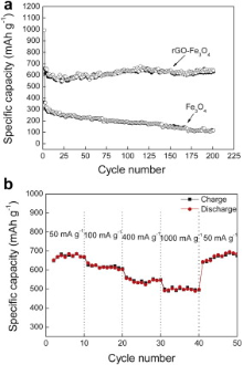
Fig. 6(a) shows the cycling behavior of rGO-Fe3O4 composite and bare Fe3O4 nanospheres at a current density of 100 mA g-1 for 200 cycles. Obviously, the rGO-Fe3O4 composite exhibits a much better cycle performance than Fe3O4. Although the discharge capacity of bare Fe3O4 electrode is 655.6 mAh g-1 in the first cycle, the capacity continuously decreases and reaches 117 mAh g-1 after 200 cycles, which is only for 17.8% of the initial capacity, indicating poor capacity retention. rGO-Fe3O4 electrode, after being decorated with rGO sheets, reveals the improved cyclic performance. The capacity of the rGO-Fe3O4 is 630 mAh g-1 after 200 cycles, 63.4% of the initial capacity (992.9 mAh g-1), which is attributed to the efficient interaction between Fe3O4 nanospheres and the rGO sheets in the rGO-Fe3O4 composite where the Fe3O4 nanospheres work as spacer between them; and both sides of rGO sheets can adsorb lithium-ion, which leads to two layers of lithium for its insertion/desertion during charging and discharging[ 38].
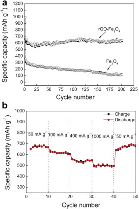 | Fig. 6. (a) Charge (solid) and discharge (hollow) capacity vs cycle number for rGO-Fe3O4 composite and Fe3O4, (b) rate performance of rGO-Fe3O4 composite. |
The rate performance during the lithium-ion insertion/extraction processes is a key factor for successful practical application as anode electrodes. Herein, rate performance of rGO-Fe3O4 composite was evaluated by carrying out charge/discharge measurements under different current densities. As shown in Fig. 6(b), the discharge capacities are retained at 689 and 616 mAh g-1 at the current of 50 and 100 mA g-1, respectively. As the current density reaches 400 mA g-1, the discharge capacity remains stable at approximately 536 mAh g-1, which is still comparable to commercial graphite electrodes. The capacity at a higher current of 1000 mA g-1, although fading, still can deliver 502 mAh g-1. It is noted that, when the current is restored to 50 mA g-1 after 40 cycles, the rGO-Fe3O4 still delivers 696 mAh g-1. The high reversible capacity, improved cycle stability and rate performance can be attributed to the high electronic conductivity of rGO sheets as substrate in the composite. rGO sheets have Li storage capacities, provide excellent electrical contact during cycling, inhibit the volume expansion and prevent Fe3O4 nanospheres from agglomeration. Meanwhile, the Fe3O4 nanospheres are homogeneously distributed in the carbon matrix, which ensures that the formed Li2O and Fe contact well without separation. All of these factors are advantageous for the kinetics toward Li insertion/extraction.
A facile and effective hydrothermal process has been developed to prepare rGO-Fe3O4 composite. The Fe3O4 nanospheres with a size of about 100-200 nm were assembled on rGO sheets uniformly, and were effectively prevented from aggregating by rGO sheets. As an anode electrode for LIBs, rGO-Fe3O4 composite exhibited higher specific capacity and better cycle stability than bare Fe3O4 electrodes. Further work to investigate the influence factors (for example, the 3D structure of graphene) on the electrochemical performance of the composite is still in progress in our group. This optimized rGO-Fe3O4 composite with enhanced performance will have a promising potential in the application of lithium-ion batteries.
This work was supported by the Fundamental Research Funds for the Central Universities (FRF-SD-12-007A), and the National Natural Science Foundation of China (No. 21276023).
| 1. |
|
| 2. |
|
| 3. |
|
| 4. |
|
| 5. |
|
| 6. |
|
| 7. |
|
| 8. |
|
| 9. |
|
| 10. |
|
| 11. |
|
| 12. |
|
| 13. |
|
| 14. |
|
| 15. |
|
| 16. |
|
| 17. |
|
| 18. |
|
| 19. |
|
| 20. |
|
| 21. |
|
| 22. |
|
| 23. |
|
| 24. |
|
| 25. |
|
| 26. |
|
| 27. |
|
| 28. |
|
| 29. |
|
| 30. |
|
| 31. |
|
| 32. |
|
| 33. |
|
| 34. |
|
| 35. |
|
| 36. |
|
| 37. |
|
| 38. |
|
| 39. |
|
| 40. |
|
| 41. |
|