


Dry Sliding Tribological Properties of a Dendrite-reinforced Zr-based Bulk Metallic Glass Matrix Composite
[Yang Huijun1, 2, *  , Liu Yong
1 , Zhang Teng1 , Wang Hengpeng1 , Tang Bin1 , Qiao Junwei2, * ]
, Liu Yong]
|
|


In the past decades, bulk metallic glasses (BMGs) have attracted a good number of interests due to their high strength, high hardness, large elastic limit, good soft magnetic as well as improved fatigue resistance in comparison with their crystalline counterparts [1]. However, almost all BMGs exhibit brittle fracture behavior at room temperature along with the fast propagation of localized shear bands, causing a catastrophic failure [2]. To achieve the toughness, a series of dendrite-reinforced metallic glass matrix composites are developed [3], [4], [5], [6], [7] and [8], which exhibit large room temperature plasticity compared to the monolithic BMGs, macroscopically characterized by the multiplication of shear bands. The attainment of toughness in metallic glass matrix composites makes them attractive for various structural engineering applications. During actual service, wear is inevitable. The crystallization of metallic glass matrix of the composites may occur during the sliding wear process, resulting in the deformation and cracking on the worn surface, which impedes their future applications as structural materials.
So far, most researchers have focused on the friction and wear characteristics of monolithic BMGs. Several results have shown that BMGs have higher wear resistance than its crystallized state [9]. Greer et al. [10] studied the wear resistance of amorphous alloys and related materials. It was concluded that the lack of work hardening capacity led to amorphous alloys having wear resistances, which were rather low in comparison with their high hardness. Amorphous alloys could undergo surface crystallization during wear; this was promoted by higher sliding speeds and was generally associated with degraded wear resistance. Crystallites larger than ∼100 nm tended to improve wear resistance, while nanometre scale crystallites may have little effect, other than by changing the properties of the matrix. Wu et al. [11] investigated the tribological property of a Zr-based bulk metallic glass. The results indicated that strain-softening occurred in the near-surface region of the BMG because of the highly localized shearing during sliding, and adhesive wear was the predominant deformation process. In addition, Wu et al. [11] calculated the contact temperature on the worn surface during sliding.
We assumed the stationary Zr-based BMG pin as material 2 and the moving flat steel disk as material 1. The maximum contact temperature rise Δ Tmax can be obtained by the following equation [12]:
where μis the friction coefficient, Vis the sliding velocity (m/s), Kis the thermal conductivity (W/(m K)), ρis the density (kg/m3), bis the radius of contact circle (mm), wis the normal load (N), the Peclet number Pe1= 9 and Pe2= 0, and p= w/π b2= 1.4 GPa.
Using the materials properties (above) in Eq.(1), the peak contact temperature rise was (above room temperature) Δ Tmax = 383 °C. If the tests were conducted at room temperature (25 °C), the surface temperature at the center of the contact area was 408 °C, which was quite close to the glass transition temperature of the BMG specimen [13].
Moreover, Lu et al. [14] compared the dry sliding wear property of dual-phase B2/body-centered cubic (bcc) Fe30Ni20Mn25Al25 nanostructured alloys at room temperature and elevated temperature. It was found that the wear rate of Fe30Ni20Mn25Al25 alloys at 673 K was much lower than that at room temperature. Oxidation played an important role in the process of the elevated temperature wear tests. Both two-body and three-body wear took place during both the room temperature and elevated temperature wear tests. Assuming that the amorphous matrix combines with bcc ductile dendrites in in-situ dendrite/metallic glass matrix (MGM) composites, what will happen during wear? Little attention has so far been paid to the tribological properties of in-situ dendrite-reinforced MGM composites.
In the present study, the tribological properties of in-situ dendrite-reinforced Zr-based MGM composites were studied. Meanwhile, the effect of applied normal loads and sliding velocities on the friction and wear performances of MGM composites was discussed in detail.
Ingots of a nominal composition (in atomic percent, at.%), Zr58.5Ti14.3Nb5.2Cu6.1Ni4.9Be11.0 was prepared by arc melting the mixture of Zr, Ti, Nb, Cu, Ni and Be with a purity higher than 99.9% (weight percent) under a Ti-gettered argon atmosphere [15]. In order to ensure the compositional homogeneity, a four-step melting procedure was adopted [16]. The liquid alloys were suctioned into a water-cooled copper mold with a cylinder diameter of 5 mm and a length of about 70 mm.
The wear testing samples were machined into a nominal cubic block sized of 10 mm (length) × 3 mm (width) × 3 mm (thickness) and well-polished with mirror surfaces. The friction and wear tests were performed by using a ball-on-block reciprocating wear test machine (MFT-R4000) as shown in Fig. 1. The tested samples were rubbed against a hardened GCr15 steel ball with a diameter of 5 mm.
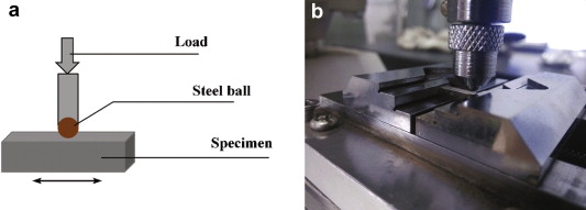 | Fig. 1. Schematic view of wear specimens (a) and wear test machine (b). |
The wear tests were carried out under dry sliding condition and the applied normal loads were 5 N, 10 N and 15 N with the different sliding velocities of the steel ball at 0.2 m/s, 0.3 m/s, 0.4 m/s and 0.5 m/s. The reciprocating amplitude and sliding time were 5 mm and 900 s, respectively. All the experiments were carried out in a normal atmosphere at temperature of 20 ± 2 °C and with relative humidity of 55 ± 5%. The steel ball and block specimens were cleaned in acetone before and after each wear test.
The friction coefficient was monitored continuously by a load cell mounted on the ball holder in conjunction with a chart recorder during the wear test. The wear volume loss of the blocks was calculated by measuring the depth and width of the wear scars using a three-dimensional (3D) surface profiler based on scanning white light interferometry. The wear rate was calculated with the wear volume loss divided by time of wear tests. The microstructure of the as-cast rods was observed by using an optical microscope. The morphology of the worn surfaces and the transverse cross-section of wear tracks were analyzed by scanning electron microscopy (SEM). The micro-hardness of MGM composites was determined by using a Vickers hardness tester (HVS-1000) under a load of 100 g for 10 s. The density of Zr-based MGM composites was measured by Archimedean principle and the accuracy was evaluated to be 0.005 g/cm3.
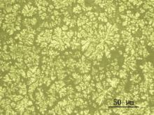
Fig. 2 shows the microstructure of as-cast MGM composites. The flowery dendrites can be found to be homogeneously distributed in the continuous glass matrix. The composition of the dendrites is rich in the elements of Zr, Ti, and Nb [17]. The diameter of the dendritic arms is about 2–5 μm, and the volume fraction is approximately 46%. The high-energy X-ray profile can be found in literature [6]. It has been demonstrated that bcc β-Zr solid solution were superimposed on the broad diffuse-scattering amorphous maxima, further identifying the two-phase structure. The micro-hardness of composites was 455 HV and the density was 6.086 g/cm3.
 | Fig. 2. Microstructure of as-cast metallic glass matrix composites. |
Fig. 3 shows the variation in friction coefficient of Zr-based MGM composites with the sliding time under different normal loads and sliding velocities. It can be clearly seen that the friction coefficient is reduced fast from a higher initial value of about 0.443 to 0.299 during the first 75 s under lower loads and sliding velocity due to the settling down of the indenter and the breaking-in of the worn surface for MGM composite to that of the steel counterpart. The initial coarse surface was smoothed owing to the higher friction during the running-in period. Then the friction coefficient fast increases up to a steady state. However, the curves are quite unstable with a great many waves caused by the rapid damage of worn surface. The friction coefficient becomes steadier with the values varying between 0.299 and 0.415. In higher normal load of 10 N, the friction coefficient slightly increases within the first 160 s and then the trend almost exhibits a steady state due to the formation of lubricating film with increasing the normal load. Furthermore, the values of friction coefficient always show a very steady status with the range of 0.30–0.43 at 0.3 m/s, attributed to more contact area between the rubbing surfaces and lubricating films. Overall, the friction coefficient shrinks in the range of 0.27–0.38 at 10 N. In addition, the curve of friction coefficient fluctuates with numerous waves in large amplitude until 290 s at 0.4 m/s. Then the trend fluctuates almost about a constant of 0.33, indicating that the running-in period was longer with the increase in the sliding velocity. The friction coefficient is between 0.235 and 0.400.
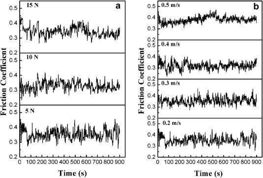 | Fig. 3. Friction coefficient as a function of sliding time for Zr-based MGM composites under different normal loads (a) and sliding velocities (b). |
The friction coefficient fluctuates frequently and falls in a flat platform after 660 s at 15 N, revealing a different friction behavior. Moreover, the phenomenon at 0.5 m/s is similar to that of 15 N. The results were explained by the fact that the lubricating film formed was destroyed by the asperities on the contact surface rapidly due to the higher normal load and sliding velocity [18]. Additionally, the friction coefficient values are high in the broader range of 0.285–0.420 and 0.310–0.450 at 15 N and 0.5 m/s, respectively.
The average friction coefficient of the dendrite-reinforced MGM composites under different loads and sliding velocities is listed in Table 1 and Table 2, respectively. It can be found that the friction coefficient of MGM composites first decreases with increasing the normal load and sliding velocity due to the integrated lubricating film formed by the compacted and grinded debris. Subsequently, the friction coefficient ascends owing to the severe damage on the worn surface at higher loading condition and sliding velocity [19]. The trend was opposite to that of brittle metal-on-metal sliding contact indicated by Parlar and Bakkal [20]. In addition, the temperature raised on the worn surface under higher loads and sliding velocities, resulting in the oxidation of some elements in the MGM composites such as Zr and Cu, which had an attraction with oxygen [21]. Thus, the friction coefficient was increased under higher loads and sliding velocities.
| Table 1. Friction coefficient and wear rate of Zr58.5Ti14.3Nb5.2Cu6.1Ni4.9Be11.0 metallic glass matrix composites at 0.2 m/s under different normal loads |
| Table 2. Friction coefficient and wear rate of Zr58.5Ti14.3Nb5.2Cu6.1Ni4.9Be11.0 metallic glass matrix composites at 5 N under different sliding velocities |
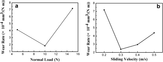
The wear rate of Zr-based MGM composites vs normal load is shown in Fig. 4(a). The constant sliding velocity was chosen as 0.2 m/s. Fig. 4(b) shows the effect of sliding velocity on the wear rate of samples under the constant applied load of 5 N. It is found that the wear rate is reduced with increasing the normal load and reaches a minimum of 1.826 × 10⁻⁴ mm3/(N m) at 10 N. Then, there is a sharp rise in wear rate above 10 N, similar to that of the friction coefficient. It is evident from Fig. 4(b) that the wear rate decreases with increasing the sliding velocity from 0.2 m/s to 0.3 m/s. Subsequently, the wear rate ascends slightly after 0.3 m/s. During the friction process, the decrease of wear rate at lower normal load and sliding velocity was attributed to the material transfer between both surfaces of the sliding counterparts and the formation of protective lubricating film on the worn surface, preventing a direct contact between two sliding surfaces [22]. However, the wear process transformed to severe wear at higher normal load, which could be explained by the fact that higher applied load led to the fracture of abrasive particles. Accordingly, they cannot be removed from the matrix, bringing about lots of large wear debris and sharp edges left on the worn surface, which was contributed to the significant increase of wear rate. In addition, the softened interface, as a result of the raised temperature on the worn surface with further increase in the sliding velocity, soon enhanced the plastic deformation of the material and increased the surface cohesion force between the composite and the steel ball, resulting in the increase of the wear rate [23].
 | Fig. 4. Wear rate as a function of normal load (a) and sliding velocity (b) for Zr-based MGM composites. |
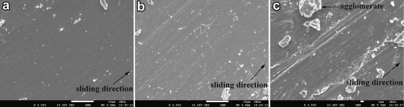
Fig. 5 shows the SEM micrographs of the worn surface on Zr-based MGM composites under different normal loads. As shown in Fig. 5(a), there are many deep and wide plowing grooves parallel to the sliding direction and wear debris particles with the shape of flakes on the worn surface, due to the protrudent bodies and the abrasive particles' plowing and scratching. Moreover, the wear debris particles are accumulated on the surface after abrasion. These are typical features associated with the abrasive wear. It is also found that there are many large and black areas as well as pocking marks on the tribosurface, showing the characteristics of adhesion mechanism. The worn surface is covered with several narrow and shallow grooves parallel to the sliding direction and less wear debris particles as shown in Fig. 5(b), which suggests a mechanism of slight abrasive wear. In addition, the lubricating film is torn slightly. Furthermore, several black areas and pocking marks are also observed on the worn surface, suggesting a mechanism of adhesive wear. It is obvious that there are lots of large wear debris scattered on the worn surface and numerous flakes like particles have agglomerated to form a large stack of wear debris, which indicates that severe abrasive wear occurs as indicated in Fig. 5(c). Moreover, some black pocking marks are also observed on the worn surface, which reveals the characteristics of adhesive wear. In Fig. 5(c), the wear scars demonstrate that the wear mechanism of composites at 15 N is abrasive wear and adhesive wear as well as delamination due to the nucleation and propagation of surface and subsurface cracks during the wear process. Furthermore, evident plastic flow appears on the worn surface as seen in Fig. 5(c) and (d), indicating a mechanism of severe adhesive wear. In addition, the material is peeled off as a result of the enough long cracks, forming the peeling pits and fracture of lubricating films on the tribosurface. Accordingly, plastic deformation occurs in the subsurface regions.
 | Fig. 5. SEM micrographs of the worn surface on Zr-based MGM composites under different normal loads: (a) 5 N; (b) 10 N; (c) and (d) 15 N. |
According to the energy transport theory of wear, in addition to plastic deformation and surface energy, some of the friction energy was transformed into heat energy [24]. The softened interface, as a result of the raised temperature, soon enhanced the plastic deformation of the material and increased the surface cohesion force between the composite and the steel ball, causing scuffing to occur [25]. Consequently, the relative motion of large-scale of adhesion conjunction or asperities resulted in the grooves on the surfaces along with the sliding direction. Besides, obvious plowing grooves and wear debris manifested that the plastic deformation took place on both sides of the grooves. Once the shallow grooves formed, the wear debris would keep in the grooves and led to local scratch, resulting in the deepening of grooves. The patches of softer Zr-based MGM composite were peeled away and formed debris under continuous operation of normal pressure and tangential friction force during sliding. Subsequently, the wear debris was transferred and cohered to the steel ball. The transferred wear debris and protrudent bodies of the steel ball acted as abrasives to abrade the surface of counterpart and cut longitudinal plowed ditches. Moreover, an accumulation of wear particles was observed on the tribosurface. These large agglomerate particles plowed across the interface and the deep grooves were formed on the worn surface, indicating that abrasive wear occurred, as shown in Fig. 5(a). In addition, the concentrated areas of local stress were formed on the tribosurface as a result of the generation for friction heat and stress. The adhesive force increased as a consequence of the cyclical stress so as to induce many large and black areas as well as pocking marks on the worn surface, which demonstrated that adhesive wear had occurred.
There were more contact areas between both surfaces of the sliding counterparts with increasing the normal load [26]. Additionally, more homogenous distribution of plastic deformation took place. Consequently, the wear course became more stable, leading to less wear debris and shallower grooves as indicated in Fig. 5(b), which decreased the friction coefficient. In addition, the wear debris of MGM composite at 10 N was made up of fine particulates and typical fragments formed by adhesive wear indicating black areas and pocking marks, resulting in a lower friction coefficient. Moreover, the lubricating film is torn slightly on the worn surface as displayed in Fig. 5(b). More plastic deformation took place on the tribosurface with increasing the normal load, leading to more softening. Accordingly, materials were peeled off easier from the wear track. Therefore, the wear rate of MGM composite was decreased with increasing the normal load. However, more severe scars and larger agglomerate were observed on the worn surface revealing its higher wear rate as the normal load was beyond 10 N. Plastic deformation can also be found with the presence of delamination in the wear tracks on the tribosurface owing to higher normal load as shown in Fig. 5(c). It is demonstrated that the normal load can produce flake-like debris as seen in Fig. 5(b) and (c). In addition, void formation, cracking and viscous flow appeared on the worn surface due to extremely inhomogeneous shear deformation under high load as displayed in Fig. 5(d). Surface intenerating took place due to the combination of friction heat and plastic deformation, resulting in the plastic flow as a rippling pattern across the tribosurface [27]. The cyclic and continuous sliding process between MGM composite and steel ball tore the lubricating film and the cracks were further extended to generate peeling-off along the cracks, forming the large peeling pit on the surface of plastic deformation material. Thus the peeling-off wear of MGM composite at 15 N led to high worn loss. The worn surface was coarse and adhesive wear was severe, making the friction coefficient fluctuate frequently at 15 N.
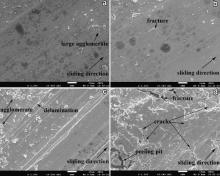
Fig. 6 shows the SEM micrographs of the transverse cross-section of a wear track during sliding of Zr-based MGM composites against steel ball under different normal loads. The feature in Fig. 6(a) includes cracks and voids generated by transfer of heavily deformed material. The river vein patterned shear bands were also observed under the worn surface that plastic deformation occurred. Fig. 6(b) shows the sign of several broad grooves and ridges on the worn surface of Zr-based MGM composite at 10 N, resulted from the plowing. Moreover, the vein pattern closer to the surface was also found in Fig. 6(b), which was smooth in a micrometer level. Some narrow and deep grooves as well as ridges on the worn surface were observed in Fig. 6(c) and (d). Furthermore, several voids and long cracks appeared in the subsurface regions at 15 N. In addition, the material was peeled off by abrasive particulates on the transverse cross-section of the composite, indicating that the dominant wear mechanism was abrasive wear at 15 N as seen in Fig. 5(d). Moreover, the cracks run through a range of depth at 15 N. There are several origins of the cracks observed on the cross-section of composites. They may have initiated at the subsurface and then propagated to the surface. Rosenfield obtained the driving force of a partially weak area under the surface to be subjected to shear instability in ductile material [28]. It is concluded that once the driving force KII whose peak was at certain depth under the surface exceeded KIIC, the cracks grew. Besides, Gilbert et al. found that crack generation in BMG was less susceptive to stress level in comparison with traditional crystalline materials [29]. Both researches showed that crack initiated in the subsurface regions near the worn surface even at low stress. Deng et al. suggested a possible mechanism that cracks propagated parallel to the tribosurface [30]. However, other studies have revealed that even though a subsurface crack originated parallel to the tribosurface under the normal pressure and tangential shear force, it eventually propagated perpendicular to the sliding surface [31]. Another explanation was that the observed cracks initiated at the worn surface and then propagated toward the subsurface area for some distance, which was in accordance with high friction coefficient values as seen in , demonstrating that the maximum shear stress turned up at the tribosurface rather than subsurface. Another possibility made by Rosenfield indicated that the deflection angle of crack propagation increased with increasing the ratio of compression stress to shear stress [32]. Therefore, the crack deflection angle was larger than 90° at 15 N as shown in Fig. 6(d). In addition, the shear bands were observed on the surface in Fig. 6 (c) and (d), suggesting that plastic deformation occurred subsurface at 15 N.
 | Fig. 6. SEM micrographs of the transverse cross-sections of wear tracks: (a) 5 N; (b) 10 N; (c) 15 N; (d) close-up view of the composite at 15 N. |
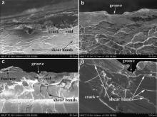
Fig. 7 shows the SEM micrographs of the worn surface on Zr-based MGM composites under different sliding velocities. As shown in Fig. 7(a), the worn surface is covered with narrow and shallow grooves parallel to the sliding direction, which are blamed for abrasive particles' ploughing and scratching. A few small wear debris with a particle-like shape can also be noticed on the worn surface. These are typical features associated with the abrasive wear. Moreover, the lubricating film on the worn surface is smooth and uniform at lower sliding velocity. Fig. 7(b) clearly shows that the plowing grooves become deeper and wider. Furthermore, some larger wear debris particles with the shape of flakes are observed on the worn surface, showing the characteristics of abrasive wear. In addition, the lubricating film breaks and splits slightly and the mild melting traces exhibit alike rectilinear direction fluid lines, suggesting a mechanism of slight adhesive wear. Consequently, the wear rate ascended with increasing the sliding velocity to 0.4 m/s. It should be noted that there is many large wear debris scattered on the worn surface and a lot of flakes like particles have agglomerated to form a large stack of wear debris, indicating that severe abrasive wear takes place as displayed in Fig. 7(c). Meanwhile, plastic deformation can also be found with the existence of delamination in the wear paths on the tribosurface due to higher sliding velocity. Besides, plastic flow is observed with the viscous fluid lines. Accordingly, the molten level deteriorated gradually with increasing the sliding velocity.
 | Fig. 7. SEM micrographs of the worn surface on Zr-based MGM composites under different sliding velocities: (a) 0.3 m/s; (b) 0.4 m/s; (c) 0.5 m/s. |
It is well-known that Zr-based MGM composites have relatively higher glass transition temperature, which can be acquired at a quite high cooling rate. Thereby, the alloy liquid was cooled down to room temperature at extremely fast cooling rate. Nucleus formation would not take place and a good deal of free volumes would be congealed in the amorphous matrix. Moreover, the energy of large-scale atomic rearrangements was also frozen. Consequently, a relatively high enthalpy value extent was obtained in the amorphous matrix. The relative sliding between GCr15 steel ball and the specimen caused the generation of friction heat on the worn surface, stimulating the metastable phase atoms to rearrange and exciting the frozen enthalpies in the amorphous matrix to be released, which led to the instantaneous fusion of contact area on the tribosurface of MGM composites. Accordingly, the heating effect was followed by surface softening and plastic flow was seen in Fig. 7(c). At lower sliding velocity, some metallic junctions welded and sheared in accordance with the welding-shearing-plowing theory, torn to form wear particles as shown in Fig. 7(a) and (b). However, the plastic flow was different from the continuous wear essentially by rearrangement of the macro-geometry on the worn surface rather than the removal of fine wear particulates at higher sliding velocity. Therefore, the governing wear mechanism transformed from abrasive wear and adhesive wear to the combination of severe abrasive wear and surface flow mechanism.
In this study, in-situ dendrite-reinforced metallic glass matrix (MGM) composites with the composition of Zr58.5Ti14.3Nb5.2Cu6.1Ni4.9Be11.0 have been prepared with a vacuum arc melter by using the copper mold suction casting. Meanwhile, the effect of different normal loads and sliding velocities on the tribological properties of composites was investigated. The conclusions are drawn as follows:
(1) The in-situ composites had a homogeneous distribution of dendrites within the glass matrix. The volume fraction of dendrites was approximately 46% and the diameter of dendritic arms was about 2–5 μm. In addition, the micro-hardness of composites was 455 HV and the density was 6.086 g/cm3.
(2) The friction coefficient and wear rate of composites initially descended with increasing the normal load and reached a minimum of 0.339 and 1.826 × 10⁻⁴ mm3/(N m) at 10 N, respectively, then ascended. Similarly, the friction coefficient and wear rate of composites initially decreased with the increase in the sliding velocity and achieved a minimum of 0.330 and 2.389 × 10⁻⁴ mm3/(N m) at 0.4 m/s and 0.3 m/s, respectively, then raised. The lubricating film formed was destroyed by the asperities on the contact surface rapidly due to higher normal load and sliding velocity.
(3) The wear mechanism of in-situ dendrite-reinforced MGM composites was mainly adhesive wear accompanied by abrasive wear at lower normal load and sliding velocity. However, the wear mechanism of composites was abrasive wear and adhesive wear as well as delamination at higher normal load and sliding velocity due to the nucleation and propagation of surface and subsurface cracks during the wear process. The flake-like and particle-like wear debris was the dominant shapes of debris observed.
References
Huijun Yang acknowledged the financial support of the National Natural Science Foundation of China (No. 51341006), State Key Lab of Advanced Metals and Materials (No. 2013-Z03), and Key Laboratory of Cryogenics, TIPC, CAS (No. CRYO201306). Junwei Qiao acknowledged the financial support of the National Natural Science Foundation of China (Nos. 51101110 and 51371122), Research Project Supported by Shanxi Scholarship Council of China (No. 2012-032), and the Program for the Outstanding Innovative Teams of Higher Learning Institutions of Shanxi (2013).
| 1. |
|
| 2. |
|
| 3. |
|
| 4. |
|
| 5. |
|
| 6. |
|
| 7. |
|
| 8. |
|
| 9. |
|
| 10. |
|
| 11. |
|
| 12. |
|
| 13. |
|
| 14. |
|
| 15. |
|
| 16. |
|
| 17. |
|
| 18. |
|
| 19. |
|
| 20. |
|
| 21. |
|
| 22. |
|
| 23. |
|
| 24. |
|
| 25. |
|
| 26. |
|
| 27. |
|
| 28. |
|
| 29. |
|
| 30. |
|
| 31. |
|
| 32. |
|