


Microstructure and Mechanical Properties of Electron Beam Welded Alloy J75
[Chen Shenghu1 , Zhao Mingjiu1, *  , Liang Hao
2 , Rong Lijian1, * ]
, Liang Hao]
|
|


Microstructure and mechanical properties of electron beam welded alloy J75 were studied under as-welded and post-weld aging treatment (PWAT) conditions. The results showed that high-quality welds were produced by electron beam welding. Under as-welded condition, a fine dendritic structure consisting of gamma dendrite matrix and Laves phase was observed in the welds. Better mechanical properties were obtained in the weld zone than that of base metal because of the fine size of the dendritic structure. After PWAT, a discontinuous distribution of γ′ particles existed in the dendritic structure. The presence of a γ′ depletion zone in the dendrite core resulted in a significant degradation of mechanical properties of the weld.
With the development of hydrogen economy, there is an ever-increasing demand for structural materials with high strength suitable for service in hydrogen environment, which motivates the development of new materials. A γ′-strengthened alloy J75, has been developed at the Institute of Metal Research, Chinese Academy of Sciences as a hydrogen resistant alloy [1], [2] and [3]. This alloy exhibits high flow stress, low hydrogen embrittlement sensitivity and excellent corrosion resistance. During the industrial application, the materials are usually joined by the process of welding to satisfy the requirement of the component design and manufacture. In view of the harsh environment in service, high-quality welds should be guaranteed in the hydrogen resistant alloys. Electron beam welding is recognized as a viable technique to solve the above problems because of low contamination, narrow heat affected zone (HAZ) and high depth of penetration [4].
As a precipitation hardened alloy, J75 is strengthened by the precipitation of ordered coherent γ′-[Ni3(Al,Ti)], which is formed during high temperature aging. Different from the base metal, microstructural evolution in welds is responsible for properties of weld zone. Investigations showed that micro-segregation and non-equilibrium phase produced during welding directly affected the microstructural evolution in the welds. Brooks and Krenzer [5] and [6] found that low melting point eutectic phase was formed in A286 during welding, which resulted in high susceptibility to fusion zone cracking and HAZ microfissuring. In Inconel 718 [7], [8] and [9] and Incoloy 903 [10] and [11], the formation of non-equilibrium solidification phases (such as MC carbides and Laves phase) during welding consumed significant amounts of the hardening element of Nb, leading to the reduced strengthening effects. Moreover, solidification-induced segregation of hardening elements was observed in the welds of the above alloys, which would affect the precipitation of strengthening phase. Therefore, a thorough understanding of the microstructure of welds is vital to establish the applicable welding process to resolve these problems.
However, rare information is available on the microstructure and properties of electron beam welded J75. In this paper, an attempt was made to clarify the microstructural evolution and mechanical properties of electron beam welded alloy J75 under as-welded and post-weld aging treatment (PWAT) conditions.
The alloy J75 was produced by vacuum induction melting technique with the chemical composition as follows: 30Ni–15Cr–1.3Mo–1.88Ti–0.36Al–0.24V–0.2Si–0.0008B–Fe bal (in wt%). The ingot was homogenized at 1433 K for 20 h, then forged and rolled into 4 mm-thick sheets. The sheets were given a pre-weld solution treatment at 1253 K for 1 h and subsequently water quenched. After milling to the thickness of 2.6 mm, the sheets were bead-on-plate electron beam welded using 60 kV and 20 mA current at a welding speed of 100 cm/min. The operating parameters were optimized through extensive weld trials in order to obtain a full penetration. Eventually, part of the welded sheets was post-weld aging treated at 1013 K for 8 h followed by air cooling.
Post-weld characterization was performed in terms of microstructure, hardness and tensile tests. Specimens for optical microscopy (OM) and scanning electron microscopy (SEM) were cut perpendicularly to the welding direction. The cross sections were mechanically polished, followed by electro-etching in a solution of 10% chromic acid. A Shimadzu EPMA (electron probe microanalyzer)-1610 electronic probe microanalyzer was used to determine the distribution of the alloying elements. Thin foils for transmission electron microscopy (TEM) were prepared from the welds to determine the secondary solidification phase on FEI Tecnai G220 TEM equipped with an energy dispersive X-ray analysis (EDX). Two types of tensile specimens with the gauge dimension of 22 mm × 4 mm × 2.6 mm were machined from the sheets: (1) base metal in solutionized and solutionized plus aged conditions; (2) transverse specimens containing the weld in the center of the gauge length. Then, some of the transverse tensile specimens with the weld were encapsulated in evacuated quartz tubes for PWAT. Tensile tests were carried out at room temperature with a strain rate of 1.5 × 10⁻³ s-1. The hardness was measured across the cross section of the weld, using a Vickers microhardness tester with a load of 500 g.
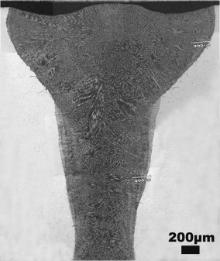
Fig. 1 shows a typical macroscopic view on the cross section of welds after electron beam welding. It can be seen that nailhead shaped weld is formed and no evidence of liquation cracking is observed in the as-welded specimens.
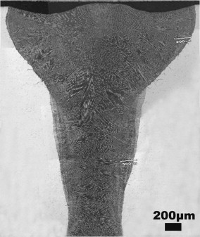 | Fig. 1. Optical micrograph of welds after electron beam welding. |
3.1.1. As-welded
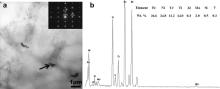
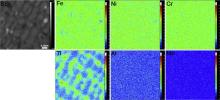
The microstructure of the as-welded fusion zone is shown in Fig. 2. A fine dendritic structure is formed in the fusion zone, as shown in Fig. 2(a). It is well-known that complete melting and resolidification occur in the fusion zone during welding. A higher magnification SEM image ( Fig. 2(b)) reveals that the solidification products consist of gamma dendrite and secondary solidification phase (marked with black arrow). The secondary solidification phase was observed to locate at the interdendritic region. In order to determine the nature of the secondary solidification phase, TEM thin foils prepared from the fusion zone were examined. Fig. 3(a) shows a bright field TEM micrograph of the solidification phase, revealing that solidification phase is formed in the interdendritic region. The inset in Fig. 3(a) shows a selected area diffraction pattern of the solidification phase and the corresponding EDX spectrum is given in Fig. 3(b). These indicate that the solidification phase is the Laves phase in the type of hexagonal MgZn2. Compared with the base metal, the Laves phase is rich in Ti, Mo and Si, and lean in Fe and Cr, which seems to the sequence of the elemental segregation during solidification. Fig. 4 shows the distribution of elements in the fusion zone after welding. It can be seen that Ti strongly segregates to the interdendritic regions while inconspicuous dendritic segregations are observed for other elements. The micro-segregation of Ti or Nb during solidification was also observed in some Fe–Ni based alloys, such as A286 [5], JBK 75 [7], Incoloy 903 [8] and [9] and Inconel 718 [10]. In addition, it can also been seen that Laves phase is formed in the region with the highest concentration of Ti, suggesting that Ti segregation determines the formation of secondary solidification phase. The Laves phase was also observed in the as-welded fusion zone of Inconel 718 [10], [11] and [12] and Incoloy 903 [8] and [9]. It was found that the Nb segregation was vital to formation of solidification phase and there was very little segregation of Ti to the Laves phase. It is suggested that the segregation of Ti also promotes the formation of Laves phase in the present work.
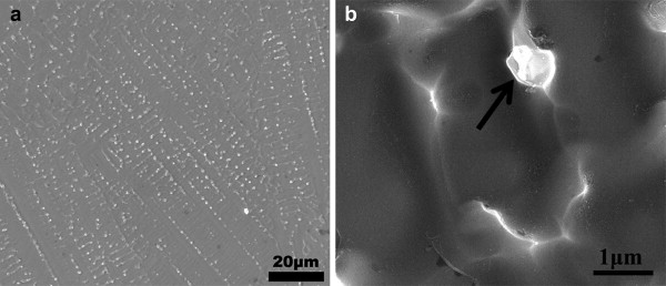 | Fig. 2. (a) SEM image showing the microstructure of as-welded fusion zone and (b) higher magnification SEM image of the dendritic structure. |
 | Fig. 3. (a) TEM bright field image and (b) EDX spectrum of the Laves phase in the as-welded fusion zone. The inset in (a) shows a [122] zone diffraction pattern of the Laves phase. |
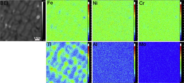 | Fig. 4. Backscattered electron image and elemental mapping images of the as-welded fusion zone by EPMA analysis. |
3.1.2. PWAT
As indicated in Fig. 2(b), γ′ particles are not observed in the as-welded fusion zone because the precipitation of γ′ is suppressed at a high cooling rate. Therefore, PWAT is usually applied to introduce the γ′ strengthening phase. However, a discontinuous distribution of γ′ particles exists in the dendritic structure after PWAT, as shown in Fig. 5(a). At higher magnification, it was clearly seen that fine spherical γ′ particles precipitate in the interdendritic region, while a γ′ depletion zone is developed in the dendrite core ( Fig. 5(b)). In addition, the dendrite core is observed to be outlined by a ring of large γ′ particles.
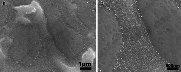 | Fig. 5. (a) SEM images showing the microstructure of fusion zone in PWAT condition, and (b) higher magnification image of γ′ particles distribution between the dendrite core and interdendritic region. |
It is well-known that the precipitation of γ′ in superalloy can be attributed to the supersaturation with respect to Al and Ti [13] and [14]. According to the elemental distribution of as-welded fusion zone in Fig. 4, Ti segregates to the interdendritic regions during solidification. The disparity in distribution of Ti between dendrite core and interdendritic region will result in different degrees of supersaturation. Higher degree of supersaturation is obtained in the interdendritic region after welding and thus high density of γ′ particles are observed. In contrast, lower degree of supersaturation in dendrite core makes it impossible for the nucleation of γ′ at the PWAT temperature.
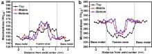
Microhardness profiles measured on three different depths of the welds under as-welded and PWAT conditions are shown in Fig. 6. As shown in Fig. 6(a), the microhardness of the weld zone is higher than that of base metal under as-welded condition. Because the width of the HAZ for electron beam welds is narrower than the area of the microindentation ( Fig. 1), the hardness of the HAZ cannot be separated from that of the base metal. After PWAT, a uniform dispersion of γ′ particles with the size of 10–20 nm is introduced in the base metal [3] and thus leads to a significant increase in the value of microhardness ( Fig. 6(b)). Meanwhile, a discontinuous distribution of γ′ particles is observed in the weld zone ( Fig. 2), so a slight increase in the hardness lever occurs after PWAT ( Fig. 6(b)). Therefore, it can be seen that the microhardness of the weld zone is lower than that of the base metal after PWAT, as indicated in Fig. 6(b).
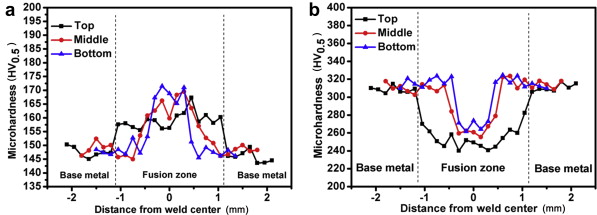 | Fig. 6. Microhardness profiles measured at three different depths of the weld under as-welded (a) and PWAT (b) conditions. |
Table 1 presents the average tensile strength of the base metal and welds under various conditions. Under as-welded condition, all the transverse specimens fractured in the base metal, outside the weld, which is in agreement with the hardness result that the hardness of the weld zone is higher than that of base metal ( Fig. 6(a)). Considering that no γ′ particles are introduced in the as-welded fusion zone ( Fig. 2(b)), the mechanical properties of welds zone are mainly determined by the size of the dendritic structure. It is found that the average secondary dendrite spacing is about 2–3 μm ( Fig. 2), which is considerably smaller than the grain size of base metal (about 50–60 μm) [15]. Therefore, better mechanical properties are obtained in the weld zone than that of base metal.
| Table 1. Tensile strength of base metal and welds at room temperature |
After aging treatment, the average tensile strengths of the base metal and weld zone reach 1067 MPa and 948 MPa, respectively (). Contrary to the as-welded condition, all the transverse specimens fractured at the fusion zone and the tensile strength of the weld zone is lower than that of the base metal. The fracture surface of the transverse specimens after PWAT reveals a number of step-like features, which is described in the published work [16]. In order to provide further insight into the fracture process, cross section through the fracture surface of the welds after PWAT was examined. A macroscopic view shows that stepped appearances are observed on the fracture surface ( Fig. 7(a)), which directly corresponds with the step-like features. A detailed investigation of the stepped appearance indicates that fracture took places by the cleavage along the interdendritic region of the cellular dendrites ( Fig. 7(b)).
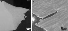
 | Fig. 7. Micrographs showing the cross section through the fracture surface of the welds after post-weld aging treatment: (a) macroscopic view of the fracture surface, (b) higher magnification image of the stepped appearance in the circle of (a). |
Taken together, the fracture process of the welds is postulated based on the microstructure and fractography analysis. Firstly, localized plastic deformation develops in the dendrite core. After PWAT, a γ′ depletion zone in the dendrite core ( Fig. 5) makes it softer than the interdendritic region and thus deformation will preferentially occur in the dendrite core. This notion is demonstrated by the image in Fig. 8(a), showing that deformation bands are highly concentrated in the dendrite core. Secondly, microcracks initiate at the boundary between the dendrite core and interdendritic region. As deformation continues, the strain concentration in the dendrite core is greater than that in the interdendritic region, requiring a corresponding strain in the interdendritic region to ensure deformation compatibility [17]. But it is impossible for the interdendritic region because the γ′ precipitates within impede the dislocation motion [18], [19] and [20]. Therefore, the stress concentration is resulted and the microcracks will be introduced at the boundary between the dendrite core and interdendritic region, as evidenced by Fig. 8(b). Finally, the microcracks propagate and connect to each other driven by the shear stress. Under tensile test, the microcracks connect to each other through shear deformation ( Fig. 7(b)), leading to the cleavage planes on the fracture surface ( Fig. 7(a)). According to the above analysis, altering the discontinuous distribution of γ′ particles in the dendritic structure is vital to the improvement in the mechanical properties of welds. Further research work is being undertaken.
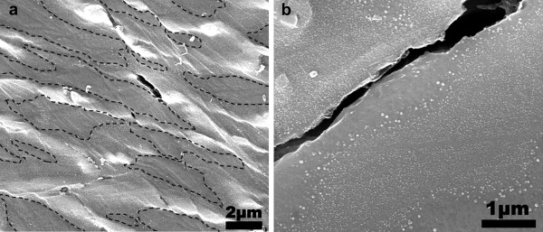 | Fig. 8. Cross sectional SEM images (a) and higher magnification image (b) near the fracture surface of the welds. In (a), the areas within the dashed lines are the dendrite cores. |
(1) Electron beam welding results in a fine dendritic structure, consisting of gamma dendrite matrix and secondary solidification phase. The secondary solidification phase formed in the interdendritic region is Laves phase, which is the sequence of elemental segregation.
(2) A discontinuous distribution of γ′ particles exists in the dendritic structure after PWAT. A γ′ depletion zone is developed in the dendrite core, which is attributed to the lower degree of supersaturation.
(3) Under as-welded condition, the microhardness of weld zone is higher than that of base metal and the fracture occurs in the base metal during tensile test. After PWAT, the microhardness and tensile strength of the welds are lower than those of the base metal.
(4) Under tensile test, the presence of γ′ depletion zone in the dendrite core after PWAT makes the deformation preferentially occur and microcracks initiate at the boundary between the dendrite core and the interdendritic region. Finally, the microcracks propagate and connect to each other driven by the shear stress.
This work was financially supported by the National Natural Science Foundation of China and China Academy of Engineering Physics (Project No. U1230118).
| 1. |
|
| 2. |
|
| 3. |
|
| 4. |
|
| 5. |
|
| 6. |
|
| 7. |
|
| 8. |
|
| 9. |
|
| 10. |
|
| 11. |
|
| 12. |
|
| 13. |
|
| 14. |
|
| 15. |
|
| 16. |
|
| 17. |
|
| 18. |
|
| 19. |
|
| 20. |
|