


Crystallined Hybrid Carbon Synthesized by Catalytic Carbonization of Biomass and in-situ Growth of Carbon Nanofibers
[Liu Shuhe1, *  , Zhao Shuchun
2 , Yao Yaochun2 , Dong Peng2 , Yang Chao2 ]
, Zhao Shuchun|
|


Crystallined hybrid carbon was synthesized by the catalytic carbonization of biomass (Pinus kesiya sawdust) at 1100 °C and in-situ growth of carbon nanofibers (CNFs) at 750 °C from acetylene. The microstructure of the composite was characterized by scanning electron microscopy (SEM), X-ray diffraction (XRD), transmission electron microscopy (TEM) and high-resolution transmission electron microscopy (HRTEM). It was found that highly crystallined carbon composed of well-aligned graphene layers with interlayer spacing of 0.34 nm can be formed by catalytic carbonization of biomass. However, the structure of the in-situ growing CNFs is less-aligned. Based on the results of the investigation, the formation mechanism of the crystallined hybrid carbon was discussed. Owning to synergistic effect of the highly crystallined carbon and the conductive network formed by CNFs, the crystallined hybrid carbon shows 32.6% lower electrical resistivity than biocarbon. When being used as anode material of lithium-ion batteries (LIBs), the crystallined hybrid carbon and the biocarbon have nearly the same first coulombic efficiencies (CEs), however, the former has a discharge capacity of 67% higher than the latter since the second cycle.
Carbon nanofibers (CNFs) and carbon nanotubes (CNTs) with a variety of novel properties, e.g., high specific modulus, strength, and surface area, high chemical and thermal stability, low mass density, and high electric conductivity [1] and [2], have been widely studied in many fields including adsorbents [3] and [4], catalyst supports [5], conductive agent [6], electromagnetic shielding or absorbing materials [7] and [8] and energy storage materials [9], [10] and [11]. However, their light weight and nano-sized structures bring shortcomings in their real applications; for example, they are hard to be dissipated and hard to be made bulk materials. So, in order to improve their dissipation, in-situ growth (thus immobilizing) on a special supporting material (macro-substrate) is highly desirable. This nano/macro composite inherits the merits of excellent properties of nanomaterials and the easy handling of macro-substrate. Further more, the macro-substrate has the synergic effect with the grown CNFs/CNTs, so it can be used in the final application and most post-synthesis processes need not to be considered. Therefore such composites deserved more and more researches these days, such as catalyst support, in waste water treatment and lithium-ion batteries (LIBs) [3], [12], [13], [14] and [15].
As chemical inert, porous structure and available in large amounts, carbon synthesized from biomass (biocarbon) is used as the macro-substrate recently. Su et al. [3] synthesized CNF(CNT)/biocarbon (activated carbon) by in-situ growth of the former on the surface and in the pores of the latter, studied the parameters influencing the morphology and the structure of the grown CNFs and the adsorption properties of the composites in waste water treatment. However, as far as we known, CNF(CNT)/biocarbon is only studied as adsorbing material, its lithium-ion storage properties are not explored yet. As is known, CNFs/CNTs as such can be used as anode materials, and their growth on micro-sized anode materials can impressively improve the electrochemical performances of LIBs by integrating multidirectional conductive network and refraining the volume change of anode particulates [13]. Moreover, biocarbon has also used as LIB anode material recently. Therefore, CNF/biocarbon might also be the LIB anode material. As for the anode materials, the crystallined carbon is beneficial to their electrical and electrochemical properties, so studies about catalytic synthesis of crystallined hybrid carbon-CNF/biocarbon, its structure, formation mechanism, and the electrical and electrochemical performances are of necessity. However, as far as we know, no such work has been reported. Here, this crystallined hybrid carbon was synthesized by using one kind of biomass (Pinus kesiya sawdust) as the raw material, and its structure, formation mechanism, electrical resistivity and electrochemical performances as LIB anode materials were explored.
20 g of Pinus kesiya sawdust was cleaned by water to remove the impurities, then air-dried at 100 °C to evaporate the absorbed water, followed by carbonization in an alumina tube at 1100 °C for 1 h, with Ar flux at 0.5 l/min, to form biocarbon. Biocarbon was further ball-milled to obtain carbon particles with d50 of 1 μm. 10 g of the milled biocarbon was vacuum-impregnated with an aqueous solution of 0.1 mol/L Fe(NO3)3·6H2O for 24 h, and then water was evaporated at 50 °C with rotary evaporator to obtain 6 wt% Fe-impregnated biocarbon. The Fe-impregnated biocarbon was further heated at 1100 °C for 1 h, with Ar flux at 0.5 l/min, in a stainless rotary bed reactor tube (inner diameter 56 mm and length 80 mm) ( Fig. 1) to form catalytically carbonized carbon (CCC). Then, As the temperature of the reactor reduced to 750 °C, in-situ growth of CNFs on CCC was done for 1 h, with the mixed gas flux of hydrogen and acetylene (volume ratio 3:1) and the rotating speed of the reactor of 0.25 l/min and 7 r/min, respectively, to obtain CNF/CCC composite. In order to homogeneously grow CNFs on CCC particles, eight stainless slabs (80 mm × 16 mm × 3.5 mm) parallel to the tube axis were welded on the inner wall of the tube to separate it into eight grooves and tumbled the particles when the reactor was rotated ( Fig. 1(b)).
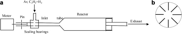 | Fig. 1. Schematic drawing of rotary chemical vapor deposition (CVD) apparatus (a) and cross-section of stainless reactor tube (b). |
All the samples were characterized by scanning electron microscopy (SEM, Nova NanoSEM 430), X-ray diffraction (XRD, D/Max2200) and transmission electron microscopy (TEM, JEOL 2010). In TEM observation, the samples were prepared by grinding biocarbon, CCC and CNF/CCC with a mortar and pestle and passing the resulted powders through a mesh sieve to obtain fine powders with diameter less than 38 μm. The fine powders were then dispersed in ethanol and ultrasonically vibrated for 3 h. With a 15-min pause to settle down larger particles, the upper part of the mixture was deposited via pipette onto a Cu grid and dried for TEM observation at 200 kV. In order to determine the relative electrical resistivity of the materials, a system consisting of nylon tube with inner diameter of 8 mm and two removable copper pistons was built and tested. The electrical resistance between the contact point of the two copper pistons was measured with a digital multimeter (Shanghai Qianfeng Electronic Instrument Co., Ltd., SD2002) while the samples in the chamber were kept under a constant pressure of 3 MPa. Electrochemical measurements were made in a two-electrode half-cell system. The working electrodes were made by mixing the as-prepared samples with carbon black and polyvinylidene difluoride in N-methyl-2-pyrrolidone in the weight ratio of 85:5:10, and then the paste was coated on copper foil to 100 μm thickness. The prepared working electrodes were dried in vacuum at 80 °C overnight and pressed. The electrode assembly was carried out in a dry glove box. The electrolyte was 1 mol/L LiPF6 in ethylene carbonate (EC) and diethyl carbonate (DEC) in 1:1 volume ratio. Celgard 2400 was used as the separator. Lithium foils were used as counter electrodes. All cells were galvanostatically discharged (intercalation) and charged (de-intercalation) over a voltage range of 0.01–2.5 V vs Li/Li+ at 30 mA/g.
Fig. 2 shows the SEM images of biocarbon (a), CCC (b) and CNF/CCC (c, d). The shapes of biocarbon particles are irregular ( Fig. 2(a)), with many pores between 7 and 10 μm, which results from carbonization of tracheid in timber of Pinus kesiya [16]. After catalytic carbonization, the irregular shapes of the particles are retained, and white dots are shown in CCC ( Fig. 2(b)), most of which are in the range of 115–829 nm, lying in the pores of carbonized tracheid ( Fig. 2(b) inset: b1). Energy dispersive X-ray spectroscopy (EDS) of the white dot reveals the presence of carbon, oxygen and iron ( Fig. 2(b) inset: b2). Iron may come from the catalyst precursor-Fe(NO3)3·6H2O, which can be identified by the comparison of components in XRD spectra of biocarbon and CCC shown in Fig. 3. Large amounts of white dots in the pores shows that the aqueous solution of Fe(NO3)3·6H2O is easy to be impregnated in the carbonized tracheid. After the CVD process, CNFs were grown on the surface of CCC ( Fig. 2(c and d)). The diameters of the CNFs are typically in the range of 150–580 nm, with a small number ones having diameters as large as ~2 μm. They tangle together and almost cover the surface of CCC, forming conductive network among CCC particles.
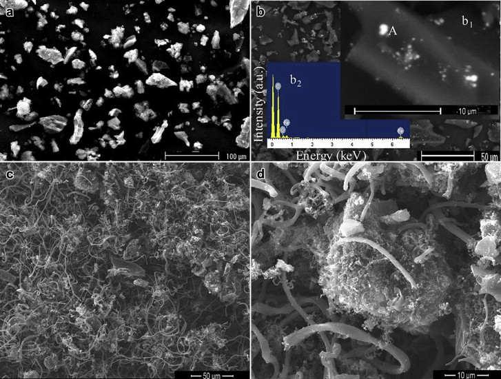 | Fig. 2. SEM images of biocarbon (a), CCC (b) and CNF/CCC (c, d). b1 corresponding to carbonized tracheid in CCC, b2 corresponding to EDS pattern of the white dot (A) in b1. |
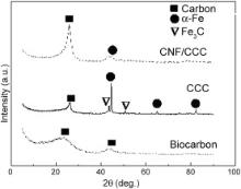
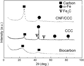 | Fig. 3. XRD spectra of the biocarbon, CCC and CNF/CCC. |
Fig. 3 shows XRD spectra of biocarbon, CCC and CNF/CCC. XRD patterns clearly change with different samples. For biocarbon, only the diffraction peaks of carbon appear; however, for CCC and CNF/CCC, except for the diffraction peaks of carbon, diffraction peaks of Fe or its compound also appear, in which the peaks at 2 θ = 44°, 65° and 82° correspond to (110), (200) and (211) facets of α-Fe (body-centered-cubic Fe) and the peaks at 2 θ = 43° and 50.8° are the diffraction peaks of Fe3C. For biocarbon, two broad diffraction peaks of carbon appear at 2 θ around 22.5° and 43°. The former can be assigned to the (002) crystal plane diffraction peak, showing presence of amorphous carbon and a low degree of graphitization; the latter can be ascribed to convolution of the (10) hk bidimensional lines, conforming the formation of a disordered carbon [17]. For CCC, the (002) diffraction peak of carbon (2 θ ≈ 26.2°) becomes narrower and sharper, and peak position shifts to that near graphite (2 θ = 26.5°), showing that a crystalline carbon structure has been formed, as confirmed by the high-resolution transmission electron microscopy (HRTEM) of CCC in Fig. 4(c–f). As for the CNF/CCC composite, the sharp peak diffraction angel (2 θ = 26.3°) is also near that of graphite, however, the peak is wider than that of CCC, implying lower crystalline structure of CNFs than that of CCC.
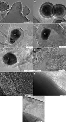
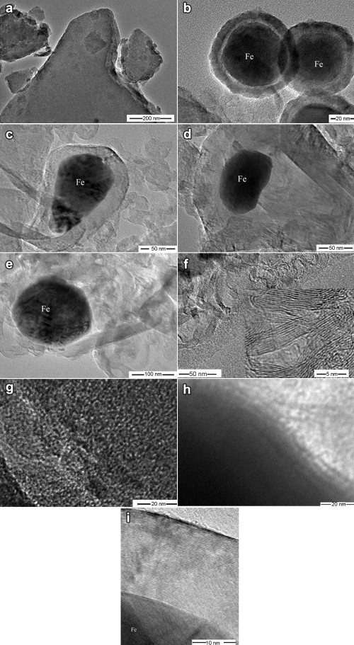 | Fig. 4. TEM and HRTEM images of biocarbon (a and g) and CCC (b–f, h and i). |
TEM images of biocarbon and CCC are shown in Fig. 4. It can be seen that the graphite layer of biocarbon is disordered and the crystalline size is small, with many pores formed from the disorderly arranged carbon layers ( Fig. 4(a and g)). After catalytic carbonization, shell–core structure of C/Fe composites is formed in CCC. The shell carbon is amorphous ( Fig. 4(b and h)) or highly crystallined ( Fig. 4(c–e and i)), enclosing nano-iron particles. In the amorphous carbon/Fe shell–core structure, the core (Fe nanoparticle) is spherical with a diameter of ca. 64 nm, and the thickness of the disordered carbon shell is 13.3 nm ( Fig. 4(b)). This kind of structure is also reported in literature [18] and [19], and the disordered shell is explained to be formed by the low catalysis ability of the small catalyst. For the crystallined carbon/Fe shell–core structures ( Fig. 4(c–e and i)), the d002 value of the crystallined carbon is ∼0.34 nm ( Fig. 4(i)), nearly being equal to that of graphite (0.335 nm), and the carbon shell is composed of 54 layers of graphite structures ( Fig. 4(c)). Fe nanoparticles of the cores are not spherical, but elongated, with the length of 100–130 nm and the aspect ratio of 1.53–1.61 ( Fig. 4(c and d)). Apart from the C/Fe shell–core structures, hollow crystallined nano-sized carbons are also found in CCC ( Fig. 4(f)). The elongated Fe particles and the void space in the C/Fe particles show that Fe nanoparticles underwent shape-varying and escaping process from the carbon shell. When the nano-iron particles escaped from the defects in the carbon shell, hollow crystallined carbons were formed [20], [21], [22], [23] and [24]. Apart from the crystallined carbon particles, around some Fe particles, carbon nanoribbons were also formed ( Fig. 4(e)), as observed by Liu et al. [25].
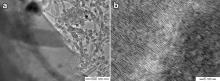
Fig. 5 shows the TEM images of CNF/CCC. It can clearly be seen that CNFs grew out on the surface of CCC. The diameters of CNFs are from 55 to 143 nm. As the CNFs are tangling together, it is difficult to measure their length. HRTEM image ( Fig. 5(b)) shows that the CNFs are of crystallined, fish-bone structure, with the graphite layers arranging nearly perpendicular to the empty axe. However, the graphite layers are less ordered than the crystallined carbon in CCC.
 | Fig. 5. TEM image of CNF/CCC (a) and HRTEM image of CNF growing on CCC (b). |
Much research on the synthesis of high crystallined carbon encapsulated nano-metals has been done with the catalytic carbonization/graphitization of amorphous carbon or carbon precursors. The formation mechanism of the highly crystallined carbon was proposed to be the dissolution of the thermally formed carbon in transitional metal nanoparticles and the following precipitation of carbon after it was saturated in them [20], [21], [22], [23] and [24]. However, few studies have been performed on the in-situ growth, and thus the formation mechanism of CNFs/CNTs on the carbon encapsulated transitional metal nanoparticles. Ivanov et al. [26] observed the continuous growth of carbon filaments after cooling and reheating the carbon-deposited metals. Morjan et al. [27] have synthesized CNTs on the shell–core C/Fe nanoparticles by catalytic laser-induced CVD, and proposed that shell–core C/Fe catalysts could provide the required conditions necessary for CNT nucleation and growth. In fact, as is known, the solubility of carbon in Fe increases with increasing temperatures. Thus, in our experiments, when the reactor temperature reduced to 700 °C, for the shell/core C/Fe samples observed by post-catalyzation HRTEM, parts of the carbon shell might dissolve in the Fe nanoparticles, thus exposing the active site (C–Fe solution) to acetylene, which making catalytic chemical vapor deposition (CCVD) and the growth of CNFs possible. Moreover, as observed from the TEM images, some Fe nanoparticles might escape out of the carbon shell, and they could also act as the catalysts for the growth of CNFs by CCVD.
With the above discussion, it can be seen that for the hybrid carbon (CNF/CCC), the crystallined carbon formation and in-situ growth of CNFs may follow the same mechanism, that is, the dissolution and diffusion of carbon into Fe nanoparticles and precipitation out of them.
The electrical resistivity and the electrochemical performances of biocarbon, CCC and CNF/CCC were compared. The disordered biocarbon exhibits high electrical resistivity (0.141 Ω cm). Catalytic carbonization decreased the resistivity to 0.118 Ω cm. In-situ growth of CNFs on CCC particles further decreased it to 0.095 Ω cm, which is 32.6% lower than that of biocarbon. As is clear, catalyzed carbonization increased the order of carbon layers in biocarbon, therefore, decreased its electrical resistivity; in-situ growth of CNFs on CCC particles can form a coherent conducting network among micro-sized CCC particles, therefore further decreased the electrical resistivity.
Fig. 6 shows the discharge–charge curves of biocarbon, CCC and CNF/CCC electrodes cycled between 0.01 V and 2.5 V vs Li/Li+ at 30 mA/g. It can be seen that the voltage profiles of all samples are nearly the same, simply composed of two parts: one is the slope region at high voltage ( V > 0.5 V), which is ascribed to the formation of the solid electrolyte interphase (SEI) layer and the filling of the micro-pores with lithium [28]; the other is the lower potential ( V < 0.5 V) region, which is due to lithium in the carbon sheets and edges [29] and [30]. The first discharge delivered specific capacity of 458.6 mAh/g and the initial coulombic efficiency (CE) is 38.3% ( Fig. 7(b)) for biocarbon, mainly resulting from high defects and micro-pores in it (as observed in Fig. 4(g)). Catalytic carbonization of biocarbon formed highly crystallined carbon with low defects in CCC; thus the discharge capacity accumulated during the first cycle decreased to 382.3 mA/g and the first CE increased by ∼10% than that of biocarbon. The in-situ growth of CNF on CCC increased the special surface area, and thus the first discharge capacity of CNF/CCC increased to 693.4 mAh/g. However, the first CE decreased to 39.8%, which was nearly equal to that of biocarbon. As the capacity of CNF/CCC is higher than those of biocarbon and CCC, it can be inferred that CNF growing on CCC has much higher capacity than biocarbon and CCC.
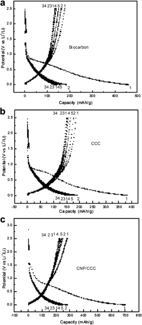 | Fig. 6. Discharge–charge curves of biocarbon (a), CCC (b) and CNF/CCC (c) for selected cycles. |
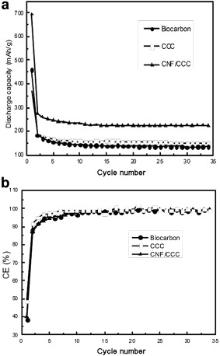
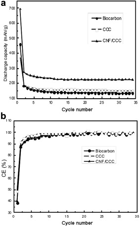 | Fig. 7. Electrochemical performance (a) and CEs (b) of biocarbon, CCC and CNF/CCC. |
Fig. 7(a) shows the discharge capacities of biocarbon, CCC and CNF/CCC in 34 cycles. The discharge capacities of all samples in the first cycles dropped rapidly, then decreased slowly in the first 10 cycles and after that remained at around 135, 144 and 225 mAh/g until the 34th cycle, respectively. Thus a highly stable reversible capacity formed after the 10th cycle, as was evidenced by the stable high CEs (nearly 98% for all samples in Fig. 7(b)) of biocarbon, CCC and CNF/CCC after the 10th cycle. Although CNF/CCC and biocarbon have nearly the same first CEs, however, the former has a discharge capacity of 67% higher than the latter since the second cycle. As a highly crystallined flaky carbon anode, natural graphite (NG) has a poor cyclability, which results from the exfoliation of carbon flakes during cycling; CNFs growing on NG can refrain the exfoliation of carbon flakes after it is intercalated by lithium, so the cyclability of NG is highly improved [13]. However, in our case, all the samples—whether the ones without CNFs (biocarbon and CCC) or the one with CNFs (CNF/CCC), have more stable cyclability than NG, and it seems that growing CNFs improves little in cyclability. As our samples are less crystallined than NG, the exfoliation of carbon flakes during cycling is thus less, which results in their better cyclability than NG and their little difference in cyclability.
With glass carbon as feedstock, Skowroński and Knofczyński have synthesized highly crystallined carbon by catalytic carbonization [31] at nearly the same temperature of ours. Its first discharge and charge capacity are 382 and 254 mAh/g, respectively, with the calculated first CE 66.5%. Compared with their results, CNF/CCC has nearly equal cycling capacity, however, its first CE is 26.7% lower than theirs. Further studies should be carried out on improving the structure of both CNF and CCC to improve the first CE and capacity of CNF/CCC composite.
Crystallined hybrid carbon was synthesized by catalytic carbonization of Pinus kesiya and subsequent in-situ growth of CNFs. Both the catalytic carbonization of biomass and the CNFs growth follow the same mechanism of carbon dissolution–diffusion–precipitation. Owning to synergistic effect of the highly crystallined carbon and the conductive network formed by CNFs, the crystallined hybrid carbon shows 32.6% lower electrical resistivity than biocarbon. When being used as anode material of lithium-ion batteries, the crystallined hybrid carbon has a discharge capacity of 67% higher than the biocarbon since the second cycle. It is believed that owing to improvement of the method presented in this paper to fabricate crystallined hybrid carbon, the decrease in irreversible capacity will be achieved, and thus a possible way can be provided for the use of biocarbon as lithium-ion anode material.
The work was supported by the National Natural Science Foundation of China (No. 51264016), the Natural Science Foundation of Yunnan Province of China (No. 2009ZC006X), the Scientific Research Foundation of Kunming University of Science and Technology, China (No. 2009-027) and the Analysis and Testing Foundation of Kunming University of Science and Technology, China (No. 2011458).
| 1. |
|
| 2. |
|
| 3. |
|
| 4. |
|
| 5. |
|
| 6. |
|
| 7. |
|
| 8. |
|
| 9. |
|
| 10. |
|
| 11. |
|
| 12. |
|
| 13. |
|
| 14. |
|
| 15. |
|
| 16. |
|
| 17. |
|
| 18. |
|
| 19. |
|
| 20. |
|
| 21. |
|
| 22. |
|
| 23. |
|
| 24. |
|
| 25. |
|
| 26. |
|
| 27. |
|
| 28. |
|
| 29. |
|
| 30. |
|
| 31. |
|