Finite Element Simulation on Thermal Fatigue of a Turbine Blade with Thermal Barrier Coatings
Yang L.1, 2 , Liu Q.X.1, 2 , Zhou Y.C.1, 2, *  , Mao W.G.
1, 2 , Lu C.3
, Mao W.G.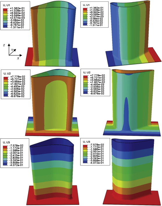
Finite Element Simulation on Thermal Fatigue of a Turbine Blade with Thermal Barrier Coatings |
|
Yang L.
, Mao W.G. |
| Fig. 4. Distribution and magnitude of U1, U2 and U3 displacements after deposition, heating, holding and cooling during the first thermal cycle in two aspect directions of a turbine blade. |
| |