Finite Element Simulation on Thermal Fatigue of a Turbine Blade with Thermal Barrier Coatings
Yang L.1, 2 , Liu Q.X.1, 2 , Zhou Y.C.1, 2, *  , Mao W.G.
1, 2 , Lu C.3
, Mao W.G.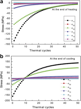
Finite Element Simulation on Thermal Fatigue of a Turbine Blade with Thermal Barrier Coatings |
|
Yang L.
, Mao W.G. |
| Fig. 10. Stress evolution with thermal cycles in region A as shown in Fig. 9 , at which stress components at the end of heating a and cooling b stages are shown, respectively. |
| |