

Bonding Interface of W-CuCrZr Explosively Welded Composite Plates for Plasma Facing Components
[Congxiao Sun, Shuming Wang , Wenhao Guo, Weiping Shen, Changchun Ge]
, Wenhao Guo, Weiping Shen, Changchun Ge]
|
|


In order to realize the effective jointing of tungsten and CuCrZr alloys manufactured for plasma facing components (PFCs), explosive welding is employed for its some unique advantages. Different welding characteristics were investigated in this study. The interfacial waveform of the welded plates changed periodically from flat-wavelet to a large wave and finally to a stable wave, which began with the detonation point. The bonding strength of the specimens is higher than 32.9 MPa. Welding hardening and the formation of microcracks occurred at the interface zone. The results demonstrate that the joining reliabilities need to be improved in order to meet the need of applications involving the use of explosive welding to fabricate tungsten-based PFCs.
In a fusion reactor such as the international thermonuclear experimental reactor (ITER), plasma facing components (PFCs) are the first barrier to protect the vacuum chamber wall and various internal components from direct high temperature plasma irradiation[1] and [2]. Typically, PFCs consist of an armor material that directly faces the plasma and a heat sink material that transfers heat loads from the armor to the water coolant. First wall materials must have good compatibility with the plasma, resistance to high heat load, high flux low-energy ion, and neutral particle irradiation. With the desirable characteristics of high melting point, low sputtering, no reactions with H, and extremely low H retention, tungsten (W) is a promising candidate for plasma facing materials in fusion test reactors[3]. CuCrZr alloys have been chosen as heat sink materials for PFCs due to several advantageous properties including high thermal conductivity, excellent welding properties, and relatively high strength. The physical properties of W and Cu differ dramatically, especially in their coefficient of thermal expansion (CTE), strength, hardness, and elastic modulus. The main difficulty in the development of tungsten-copper jointing is the large thermal expansion mismatch, which generates high joint interface stresses during jointing. The heat removal capabilities and the thermal fatigue performance of the PFCs depend on the reliability of the jointing. Therefore, the design and realization of the reliable jointing of PFCs are crucial issues[4] and [5].
Explosive welding is suitable for the joining of a wide range of metals, especially metals with great differences in melting point and CTE, so it is generally used to bond two dissimilar metal plates and is most often used when the joining is impractical by conventional welding[6] and [7]. The quality of the joint is usually excellent, having high mechanical strength. Because it is a “ cold method” , the bonded metals retain their original properties. So the effective connection of W and CuCrZr can be attained by explosive welding[8] and [9].
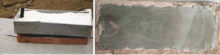
The parameters of the W and CuCrZr plates used are shown in Table 1, and their dimensions are 150 mm × 60 mm × 1 mm and 150 mm × 60 mm × 20 mm, respectively. The stand-off distance was 5 mm, which was calculated by the empirical formula h0 = 0.2 (δ 1 × δ 0) (mm) [10]. Ammonium nitrate fuel oil (ANFO) was used as the explosive and salt with perlite were added to adjust the explosive density. The calculated detonation velocity was 1900 m/s and 2400 m/s, respectively. The surfaces of the flyer and base plates were polished by grinding wheel. The explosion tests were carried out on cardboard embedded in a sand pool. Experiments were performed using a parallel plate arrangement, and the explosive was lighted at the middle of short edge. The welding aperture and the explosive welded sample are shown in Fig. 1.
| Table 1 Parameters of W and CuCrZr plates used |
The as-prepared samples were characterized and analyzed by scanning electron microscopy (SEM, Quanta 400F). The interface microhardness and the bonding strength were measured under an MH-6 sclerometer and a Universal Material Testing Machine respectively.
 | Fig. 1 Welding aperture and the explosively welded sample. |
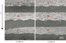
The interface microstructures of the explosively welded W/CuCrZr were observed by SEM, and the phenomena of melting and metal plastic deformation were analyzed. Samples were cut along the direction of detonation propagation, and the front, middle and end positions of composite plates were chosen. Fig. 2 shows the SEM images of the interface waves of the samples. The left and right columns of images represent the interfaces for which the detonation velocity (Vd) was 1900 m/s and 2400 m/s, respectively. A, B and C represent the front, middle and end positions of the interface. There are various types of interfaces, including straight, smooth, shallow, and wavy [11] and [12]. In this case, more than one type of profile was present in the same sample. At the beginning, the joint interface was straight, and then began to form the regular wavelets. The wavelength and amplitude increased gradually with the increase of distance. Then the wave began to weaken and cracks formed at the end of the clad board. Interface waves are formed when the flyer collides with the base plate at high speeds, causing large plastic deformation [13]. At the beginning of the detonation, the impact energy was small and unstable, so the interface was straight and irregular. With increasing explosive load and impact velocity, the pressure pulses have little time to increase, and have a relatively short time to decay (over a period of about 100 μ s) [14]. The peak amplitude increased from the detonation point for the first 60 mm and then remained at a relatively constant level. The downward velocity of the flyer plate followed a similar pattern. The maximum impact velocity was relatively low near the detonation point, but then gradually increased until it reached a constant value at the position about 60 mm from the detonator. Due to the large shear impact force, the cracks formed near the end of the detonation [15] and [16].
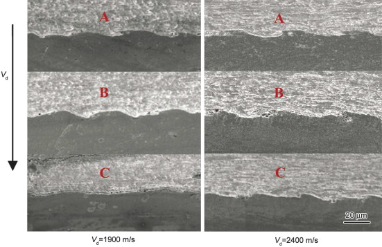 | Fig. 2 Welding interface for different Vd: (A) front; (B) middle; (C) end. |
Fig. 3 shows the peaks of waves and vortices at the joint interface. Various degree of plastic deformation can be observed at different interfacial positions. Grains of tungsten close to the interface are elongated in a certain arrangement, forming a flowing layer along the interface. Areas far from the interface experience almost no grain deformation. As strong plastic shearing occurred at welding interfaces, and shearing energy was converted to heat energy, causing the interface temperature to rise sharply. This increase caused matrix grains to revert and recrystallize, resulting in a streamlined microstructure.
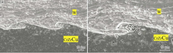 | Fig. 3 Enlarged view of the combination. |
As shown in Fig. 3(b), there are discontinuous melting layers and melting blocks along the interface, the former were caused by the heat generated in plastic deformation, while the latter were caused by the heat generated in the adiabatic compression of air. In both cases, they were all produced at high temperature, and then melted and cooled at a high speed. The molten metal was distributed evenly around the wave edges. Due to the effects of the detonation energy, molten metal gathered in the minimum pressure area of the vortices at the front, along the direction of the detonation wave, with the formation of the waveform. Molten blocks distributed discontinuously and occupied small areas. In the process of explosive welding, the vertex that is a consequence of metal jetting has a great effect on bonding strength. The vertex can wrap around hard brittle intermetallic compounds due to the high temperatures and pressures of explosive welding. In addition, a vertex can reduce the adverse effects that maybe associate with the explosive bonding interfaces. Because of their dual character, the amount of vortices should be carefully controlled[17].
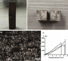
Tensile specimens were taken from the front, middle, and end positions of the explosively welded composite plates, and the tensile surface was 10 mm × 10 mm in area. In this experiment, the W/CrZrCu bonding strength was measured under a Universal Material Testing Machine. Because the 1 mm flyer plates could not be firmly fixed by the jig, 7-Epoxy adhesive was used to fasten the samples on loading blocks. The stretched sections are shown in Fig. 4.
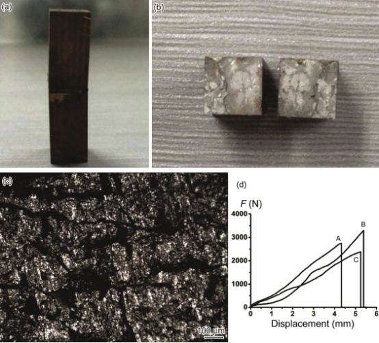 | Fig. 4 Tension test of the specimens. (a) Bonding block of the composite board and the loading block; (b) macrograph of sections after tension test; (c) photograph of the magnified interface; (d) force-displacement curves of specimens taken from different positions A, B and C. |
Brittle fracture occurred for tungsten plate, which is shown clearly in Fig. 4(b) and (c). No interfaces of W/CrZrCu and flyer/loading blocks were separated, and the maximum value of tensile strength was 32.9 MPa. The data suggest that residual stress remained in the tungsten plate, resulting in cracks and fracture. Because there was no welding interface separation, the tensile strength only indicates the fracture strength of the tungsten plate. The interface bonding strength should be greater than 32.9 MPa. Therefore, reducing residual stress and cracks of the tungsten plate, which are produced in the process of explosive welding has become a difficulty[18]. In order to reduce the brittleness and increase the toughness of the tungsten plate in the process of explosive welding, it is beneficial to heat tungsten plate first[19]. However, when it is heated in air, the tungsten flyer is easily oxidized. In addition, the explosives cannot bear such high temperature. Therefore, the problem has not been solved.
3.3. Interface microhardnessTest samples were obtained along the detonation direction at the same positions based on initial points, but at different detonation velocities. The testing loads on the tungsten and CuCrZr plates were 200 g and 50 g, respectively, and the holding time was 15 s Fig. 5 shows the microhardness graph at the bonding areas.
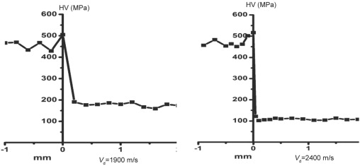 | Fig. 5. Interface microhardness curve of the explosively welded W/CuCrZr composite plates. |
The microhardness value at the interface is the largest in comparison with those of other areas in Fig. 5. The high impact velocity created large plastic deformations, which in turn produced varying degrees of work hardening on both sides of the interface. The more severe the plastic deformation, the greater the hardness of the interface[20]. The degree of the welded interface plastic deformation can be described by the microhardness of interface; the microhardness value of the bonding zone can also be used to judge the bonding strength of the composite plates. Investigation shows that the welded metals have higher bonding strength when waveform developed fully. In addition, the microhardness value of interface can guide its subsequent process and application[21].
Explosive welding was used to joint tungsten and a CuCrZr alloy. There are several important characteristics of this welding. The waveform trend from the initial point begins as flat-wavelet, then progresses to a medium wave, then a large wave, and finally a stable large wave. As the distance from the initial point increases, the wavelength and amplitude gradually increase. Large interface plastic deformation led to an increase in the wavelength and amplitude. Welded metals have higher bonding strengths once the waveform has fully developed. The bonding strength of the W/CrZrCu explosive welding interface is greater than 32.9 MPa. Fracture occurred in the tungsten plate in the tensile test, which indicates the tungsten plate is more apt to crack due to the residual stresses that result from explosive welding. Reducing this residual stress has become a major issue that must be resolved in order to increase the tensile strength.
The authors have declared that no competing interests exist.
| [1] |
|
| [2] |
|
| [3] |
|
| [4] |
|
| [5] |
|
| [6] |
|
| [7] |
|
| [8] |
|
| [9] |
|
| [10] |
|
| [11] |
|
| [12] |
|
| [13] |
|
| [14] |
|
| [15] |
|
| [16] |
|
| [17] |
|
| [18] |
|
| [19] |
|
| [20] |
|
| [21] |
|