


Microstructure, Interface, and Properties of Multilayered CrN/Cr2O3 Coatings Prepared by Arc Ion Plating
[Chang-Ming Shi, Tie-Gang Wang , Zhi-Liang Pei, Jun Gong, Chao Sun]
, Zhi-Liang Pei, Jun Gong, Chao Sun]
|
|


There has been much interest in developing multilayered or nanolayered physical vapor deposition (PVD) coatings identified as a group of promising protective coatings for their excellent mechanical properties and corrosion resistance. In this study, the multilayered CrN/Cr2O3 coatings with different bilayer periods ( Λ) were synthesized on the polished high speed steel substrates from a Cr target with the alternative atmosphere of pure nitrogen and pure oxygen by arc ion plating (AIP) technique. The results revealed that the microstructure, morphologies and properties of the multilayered coatings were strongly influenced by the bilayer period ( Λ). There were two kinds of interfaces in the multilayered CrN/Cr2O3 coatings: the sharp ones and the blurry ones. With reducing the value of Λ, the macro-particles densities decreased gradually, whereas the coating microhardness, adhesive strength and wear resistance first increased, and then decreased slightly or remained stable as the bilayer period Λ < 590 nm. The multilayered CrN/Cr2O3 coating with the bilayer period Λ of 590 nm possessed the best comprehensive properties, namely the highest microhardness, the strongest adhesion, and the lowest wear rate.
CrN and Cr2O3 being two kinds of typical Cr-based protective coatings, have been widely used in many industrial fields due to their attractive properties, such as strong adhesion, good toughness and corrosion resistance, chemical inertness, mechanical strength, optical characteristics, high hardness and low friction coefficient[1], [2], [3] and [4]. However, the hardness of CrN coatings needed to be further improved for its wide industrial applications. On the other hand, the chipping and radical brittle failures of Cr2O3 coatings on the tool steel substrate often happened due to its brittleness and high residual stress level[5].
In order to improve the poor adhesion of Cr2O3 coating to substrate and to further improve the hardness of CrN coating, CrN/Cr2O3 composite coatings, mainly in the form of double-layered or duplex coatings, have been developed using arc[6], [7], [8], [9] and [10] or sputtering[11] and [12] methods in recent years. The CrN/Cr2O3 duplex coatings have exhibited better performances than the single CrN coatings and the Cr2O3 coatings, such as higher hardness and stronger adhesion, as well as excellent wear resistance. These advantages resulted in some possible industrial applications of such “ duplex” coatings (e.g. as release mold coatings for aluminum die casting or injection applications)[7] and [12].
During the past several years, many composite coatings in the form of multilayered, nanolayered or super lattice have been developed rapidly due to their excellent mechanical properties and corrosion resistance[13], [14], [15], [16] and [17], such as multilayered Cr/CrN coatings[14], multilayered f-TiN/h-AlSiN films[16], CrN/Mo2N multilayers[18], nanolayered TiN/AlN coatings[19], and CrN/AlN super lattice films[20]. The advantages of two components in these multi- or nano- layered coatings were shown, even beyond their individual strengths, which resulted from the reduction of scale or size.
Similarly, the multilayered CrN/Cr2O3 coating would combine the merits of the CrN and Cr2O3 layers more effectively, which can be used as a potential protective coating with better performances. However, there are few studies on the preparation, microstructure and properties of the multilayered CrN/Cr2O3 coatings. The aporia could be attributed to the control of the broadening interface between the oxide layer and the nitride layer, which resulted from the high activity of oxygen. In this work, the multilayered CrN/Cr2O3 coatings with various bilayer periods (Λ ) but the same total thickness were prepared by arc ion plating (AIP) technology in an alternative atmosphere of nitrogen and oxygen from a Cr target. And the effects of bilayer period (Λ ) on the microstructure, interface, morphologies, as well as mechanical and tribological performances of multilayered CrN/Cr2O3 coatings were investigated systematically.
The multilayered CrN/Cr2O3 coatings with various bilayer periods (Λ ) were deposited on high-speed-steel (HSS) (W6Mo5Cr4V2-M2 HSS: 0.9% C, 6.1% W, 5.0% Mo, 4.1% Cr, 1.95% V, Fe balance (in wt%); 64-66 HRC at room temperature) discs (20 mm × 20 mm × 3 mm) by AIP system from a Cr target (99.9% purity) with a diameter of 64 mm. The substrates were mirror-polished to Ra < 0.05 μ m, followed by wet cleaning in an ultrasonic bath of acetone and alcohol for 15 min each, then were dried and fixed onto the rotating substrate holder at a distance of 130 mm from the target in the vacuum chamber. With the alternative atmosphere of pure nitrogen and pure oxygen (99.99% in purity) controlled by mass flowmeters, the deposition procedures of CrN and Cr2O3 layer were repeated to prepare multilayered CrN/Cr2O3 coatings following the Ar+ bombardments and Cr interlayer depositions. During the whole deposition procedure, no additional heating was applied to the specimens. The temperature near the substrates rose up to ∼210 ° C from room temperature during the Ar+ bombardments, and then decreased to ∼175 ° C in the coating deposition. In view of the insulativity of the Cr2O3 phase at low temperature, once the arc was extinguished, it was very difficult to be re-generated. The CrN layer of next period was deposited continuously on top of the former Cr2O3 layer to maintain the arc. In addition, the interface adhesion between the Cr2O3 layer and CrN layer would be enhanced by the existence of small amount of residual oxygen, which participated in forming the Cr-O-N bonds. By adjusting the deposition time of CrN and Cr2O3, respectively, the monolayer thickness was controlled. All the deposition process of the multilayered CrN/Cr2O3 coatings was started from the CrN layers after the deposition of the Cr interlayer, which was used to improve the adhesion with the HSS substrates, and ended at the Cr2O3 layer. The total thickness and the thickness ratio of CrN vs Cr2O3 layer of all the coatings were kept about 3.5 μ m and 1:1, respectively. The deposition details are summarized in Table 1.
| Table 1 Details of deposition parameters of the multilayered CrN/Cr2O3 coatings by arc ion plating technique |
The as-deposited multilayered CrN/Cr2O3 coatings were analyzed by X-ray diffraction (XRD; D/MAX-RA of Rigaku, Japan) with monochromatic CuKα (λ = 0.154056 nm) radiation operated at 50 kV and 300 mA. The diffraction angle (2θ ) of the scanning scope ranged from 20° to 85° with a 0.02° step size and 4° /min scanning speed. Scanning electron microscopy (SEM; INSPECT F, FEI) was used to observe the cross-sectional and surface morphologies, and to measure the thickness and bilayer period (Λ ) of each multilayered coating. The densities and the diameters of the macro-particles on the surface of the multilayered coatings were counted using a metallographic image analysis software (SISC IAS V8.0, Beijing KYKY Comp. Technol. Ltd. Co, China). X-ray photoelectron spectroscopy (XPS; ESCALAB250 of Thermo VG, USA) was used to analyze the depth profile of a typical multilayered coating (Λ = 590 nm). Cross-sectional morphologies and high-resolution (HR) images of the interface in the typical sample were observed by transmission electron microscopy (TEM; Tecnai G2 F30).
A Knoop diamond microhardness tester (LM 247AT, LECO Co. Ltd., US) was used to evaluate the microhardness of all the as-deposited multilayered coatings under a load of 25 g and a dwelling time of 15 s. The adhesive strength of all the specimens were evaluated via scratch tests using a multifunctional test instrument of materials surface properties (MFT-4000, Lanzhou ICP, CAS, PR China) with a Rockwell C diamond stylus (cone apex angle: 120° ; tip radius: 0.2 mm). The loading rate, translation speed, termination load and scratch length were 100 N/min, 0.083 mm/s, 100 N and 5 mm, respectively.
Rotating sliding wear tests against alumina balls (4 mm in diameter) in the form of the traditional ball on disk were performed on a classical rotating friction tester (MS-T3000, Lanzhou ICP, CAS, PR China) to characterize the tribological behaviors of all the multilayered coatings under ambient atmospheric conditions (25 ± 5 ° C and 40 ± 5% RH). The normal load, rotating speed, rotating radius and the testing time for each sample were 5 N, 200 r/min, 6.5 mm and 60 min, respectively. The average friction coefficients were calculated from the steady-states (from 10th to 60th min in this work) in the frictional coefficient curves. The specific wear rate k can be calculated according to Archard's classical wear equation [21]:
equation(1)


where V is the wear volume calculated by the cross-area of wear tracks, which was measured by using a Stylus Profiler tester (Alpha Step IQ, KLA-Tencor Co. Ltd., US), and S and L are the total sliding distance and the applied load, respectively. The worn track morphologies of all multilayered coatings after the wear tests were also observed by scanning electron microscopy coupled with energy dispersive spectrometer (EDS; Oxford ISIS, UK) system.
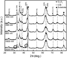
Fig. 1 illustrates the XRD patterns of the multilayered CrN/Cr2O3 coatings with varying bilayer period (Λ ) deposited on HSS substrates. These were composed primarily of the rhombohedral Al2O3 type Cr2O3 phase (JCPDS No. 82-1484) and the B1-NaCl type CrN phase (JCPDS No. 77-0047). There was no other distinct diffraction peak except a weak peak of Cr2N (111) at 42.5° (JCPDS No. 35-0803) and a small peak of CrO3 (200) at 30.9° (JCPDS No. 32-0285), which only appeared in the diffraction pattern of the coating at Λ = 3520 nm. All the multilayered coatings were crystallized well. With decreasing the bilayer period (Λ ), the peak intensity of (200) diffraction peak for the CrN phase increased significantly, and the preferred orientation of Cr2O3 phase changed gradually from random orientation to (104), and then to (110) at last. Since the penetration depth of X-ray kept constant in all case, the peaks of CrN in the multilayered coatings with larger bilayer periods (Λ = 3520 nm and Λ = 1800 nm) were relatively weaker than those in other coatings.
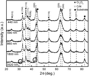 | Fig. 1 XRD spectrum of the multilayered CrN/Cr2O3 coatings with various bilayer periods (Λ ) |
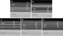
The cross-sectional SEM micrographs of the multilayered coatings with different bilayer periods are shown in Fig. 2. It can be seen from Fig. 2(a) to (d) that there were two kinds of obvious compact layers with sharp interface, which adhered well to the substrates. Neither pinholes nor pores can be observed in the cross-sectional images. According to the deposition procedure and the XRD analysis results, it can be identified that the bright layers were CrN, while the dark layers were Cr2O3. The interfaces of the coating with bilayer period Λ = 440 nm became blurred slightly due to the hysteresis phenomenon during alternating reactive gas, as displayed in Fig. 2(e).
 | Fig. 2 SEM micrographs of the polished cross-section of the multilayered CrN/Cr2O3 coatings with various bilayer periods (Λ ): (a) 3520 nm; (b) 1800 nm; (c) 860 nm; (d) 590 nm; (e) 440 nm. |
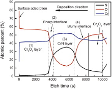
The element depth distribution of the top 1.5 periods of the multilayered coating with Λ = 590 nm etched with 3 keV Ar+ for 10490 s by XPS is illustrated in Fig. 3. The top period can be divided into four zones according to the composition, which are (1) Cr2O3 layer, (2) CrN-Cr2O3 sharp interface, (3) CrN layer and (4) Cr2O3-CrN blurry interface. In the Cr2O3 layer, the composition ratio of Cr:O was close to 2:3, which suggested that the Cr and O reacted completely to form Cr2O3. In the CrN layer, however, there was still ∼12% O. This may be due to the “ edge effect” that the edge of X-ray detecting spot excited a small part of the photoelectrons of the sputtered side wall of Cr2O3 layer. Therefore, the width of the interfaces, especially the CrN-Cr2O3 sharp interface, may be narrower in fact than that presented in Fig. 3.
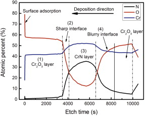 | Fig. 3 XPS depth profile of a typical multilayered coating with Λ = 590 nm. |
In order to study the interfaces between CrN layer and Cr2O3 layer in detail, morphologies of the interfaces produced by HRTEM are shown in Fig. 4. The dark field image at low magnification is shown in Fig. 4(a), from which it can be seen obviously that there were two kinds of interfaces between the layers, which could be defined as the “ sharp interface” and the “ blurry interface” . From the HRTEM images of Fig. 4(b), two well-crystalized layers and an interface between them can be observed clearly. The width of the interface between the CrN layer and Cr2O3 layer could be estimated only to be 1-2 nm. By measuring the interplanar spacing coupled with the diffraction points as shown in the insets of the fast-Fourier transformation (FFT) patterns marked as zone A and B, CrN (111) (200) and Cr2O3 (104) (110) can be calibrated, respectively, which were well consistent with the XRD results as illustrated in Fig. 1. The morphology of the blurry interface between Cr2O3 layer and CrN layer are shown in Fig. 4(c), whose width was approximately 40-50 nm or more (there was no obvious border between the interface and the Cr2O3 layer). Fig. 4(d) shows the HRTEM image and relevant FFT pattern of the inside of the blurry interface (marked as zone C in Fig. 4(c)). Some fragmentary nano-crystals and large area of near-amorphous structure can be observed. The crystallinity and the grain size in zone C were much smaller than that in zone A and B. The FFT pattern consisted of several weak diffraction points and a halo pattern. So, the microstructure of the blurry interface could be nano-crystals dispersed in an amorphous matrix, because the excess O in the B1-Cr(O, N) solid solution diffused toward the grain boundary, and amorphous CrOx segregated on the grain boundaries[22] and [23].
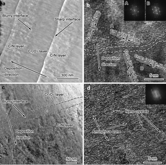 | Fig. 4 TEM and HRTEM images and corresponding FFT patterns of the interfaces in the multilayered CrN/Cr2O3 coating with Λ = 590 nm: (a) dark field image at low magnification; (b) HRTEM image of sharp interface; (c) and (d) bright field and HRTEM images of blurry interface. |
The difference in width of the interfaces between CrN layer and Cr2O3 layer resulted from different activities of O and N. The CrN-Cr2O3 sharp interface formed after the deposition of the former CrN layer, before the Cr2O3 layer. Once O2 was fed into the deposition chamber, it would react with Cr to form Cr2O3 immediately, not with N2 even there was some residual N2 because of the higher activity of O2 than that of N2. However, the Cr2O3-CrN blurry interface formed after the deposition of the former Cr2O3 layer, before the CrN layer. When the O2 flow was cut off and N2 was introduced into the vacuum chamber, the residual O2 would still have priority to react with Cr. As the residual O2 was removed by the vacuum pump gradually, the reaction between O2 and Cr got weaker, while the reaction between N2 and Cr got stronger. As a result, the Cr2O3-CrN interface was broadened to Cr-O-N gradient layer. It could be concluded that the formation of the blurry Cr-O-N gradient interlayer covered most of the deposition procedure with decreasing the bilayer period Λ . Namely, the proportion of the blurry interface containing nano-crystals and amorphous matrix in the whole coating would expand, which could result in the reduction of the differences in the composition of the two layers, whose effects on the microhardness of the coatings will be discussed in Section 3.2.
Fig. 5 shows the SEM micrographs of surface morphologies of the multilayered CrN/Cr2O3 coatings with different bilayer periods (Λ ). It can be observed that a serious spalling occurred on the surfaces of the duplex coating as shown in Fig. 5(a), which was caused by the accumulation of the internal stress up to a very high level during the deposition of Cr2O3 coatings by arc ion plating [1]. Compared to the image in Fig. 5(a), the flaking reduced rapidly in Fig. 5(b), and disappeared finally in Fig. 5(c), (d) and (e). It suggested that the internal stress in the multilayered coatings was relieved more effectively by decreasing the bilayer period under the same thickness ratio of CrN vs Cr2O3 layer. From Fig. 5, it can also be seen that there were a number of macro-particles and pits (or pinholes) ranging from hundreds of nanometers to several micrometers on the surface of the multilayered coatings, which was a common phenomenon on the surface of coating prepared by AIP technology [24] and [25]. It seems that most of the droplets emitted from the arc spots on the surface of Cr target have been solidified before they arrived at the substrates judged from their sphericity morphologies, mainly due to the high melting point of the reaction product Cr2O3. The macro-particles shrank at the ambient temperature cooling after the depositions. Since the macro-particles possessed larger specific areas than the coating around them, they shrank more obviously and flaked from the surfaces resulting in the pits and pinholes left on the coatings.
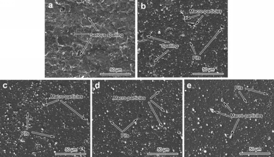 | Fig. 5 SEM images showing surface morphologies of the multilayered CrN/Cr2O3 coatings with various bilayer periods (Λ ): (a) 3520 nm; (b) 1800 nm; (c) 860 nm; (d) 590 nm; (e) 440 nm. |
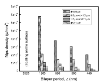
For comparison, the densities and diameters of the macro-particles on the surfaces of the multilayered coatings shown in Fig. 5(b-e) are counted and illustrated in Fig. 6. All the macro-particles on each surface of the multilayered coating were divided into four groups according to the diameter d, that was d < 0.6 μ m, 0.6 μ m < d < 1.2 μ m, 1.2 μ m < d < 2.1 μ m and d > 2.1 μ m. It can be found from Fig. 6 that the diameter of most macro-particles on the sample surfaces was d < 0.6 μ m, and the densities of the macro-particles reduced with the decrease of the bilayer period, especially for the macro-particles with the size of d < 0.6 μ m. It was attributed to the different extents of the “ effective target poisoning” caused by the Cr2O3 insulating layer formed on the target surface with the different deposition time of the top Cr2O3 layers. In the short deposition time of the top Cr2O3 layer (Λ = 440 nm), the temperature of the target surface was quite low because of the less thermal accumulation, and a Cr2O3 insulating layer was formed on the target surface. The insulating layer, usually named as “ target poisoning” , could make it difficult form the macro-particles. With the prolongation of deposition time of the top Cr2O3 layer (Λ > 440 nm), the thermal accumulated on the target surface got more, so that the temperature became higher. The insulating layer on the target surface could be molten and sputtered away from the target surface more easily by the arc discharge force. In this case, more macro-particles formed with the less “ effective target poisoning” .
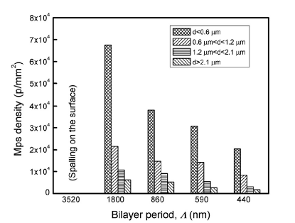 | Fig. 6 Densities and diameters of the macro-particles (mps) on the surfaces of the multilayered CrN/Cr2O3 coatings as a function of bilayer period (Λ ). |
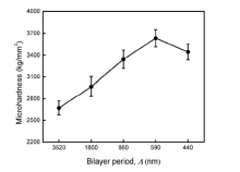
Fig. 7 illustrates the changes on the microhardness of the multilayered coatings as a function of bilayer period ranged from 3520 nm to 440 nm. With the decrease of the bilayer period from 3520 nm to 440 nm, the microhardness rose and reached the highest value of 3634 kg/mm2 at 590 nm of the bilayer period, and then declined to 3444 kg/mm2 at 440 nm. The multilayered coatings at 860 nm, 590 nm and 440 nm bilayer periods exhibited higher microhardness than that of the AIP Cr2O3 coating and the CrN coating (3281 kg/mm2 and 2293 kg/mm2, respectively) deposited under the same conditions as shown in Table 1. The enhancement of microhardness during the former stage mainly resulted from the strengthening from the modulus difference[26]. In this study, the differences in the shear modulus of the two materials (CrN and Cr2O3) were proportional to an energy difference, which the dislocations had to overcome for penetrating the interface between two layers. Compared to the single Cr2O3 coating, the insertion of CrN layers into the Cr2O3 layers changed the shear modulus differences. With decreasing the bilayer period of the multilayered coating, more interfaces were introduced into the coatings. The distance of the dislocations movement was shortened sharply, and it was more difficult for the dislocations to move across the interfaces. Therefore, the number of the available dislocations was reduced at the interfaces, and larger force was required to cause deformations.
 | Fig. 7 Microhardness of the multilayered CrN/Cr2O3 coatings as a function of bilayer period (Λ ). |
With the further decrease of the bilayer period Λ , the microhardness of the coatings declined from the peak value to 3444 kg/mm2. The reason is the narrowing of the differences in the composition of the two layers as discussed in Section 3.1. As mentioned before, the proportion of the blurry interface (Cr-O-N gradient layer) in the whole coating increased gradually since the individual layer became thinner and thinner. At the same time, the purity of the CrN layer or Cr2O3 layer dropped down. Therefore, the difference of the shear modulus in the multilayered coating was diminished, resulting in the energy reduction of most dislocations movement between the two materials (Cr-O-N and Cr2O3 or CrN), thus providing the transition for the dislocation to penetrate the Cr2O3-CrN interface. The dislocations could penetrate the interface more easily, so the microhardness declined.
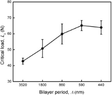
The scratch tests were carried out to evaluate the adhesions (critical loads) of the multilayered CrN/Cr2O3 coatings to the HSS substrates. The adhesive strength of the multilayered CrN/Cr2O3 coatings is illustrated in Fig. 8. With the decrease of the bilayer period, the adhesion increased remarkably, and reached a plateau region when the bilayer period was less than 590 nm. The enhancement of the adhesive strength could be attributed to two aspects. On the one hand, the residual stress in the coatings could be reduced by decreasing the bilayer period in hundred(s) nanometers scale. Similarly, Lousa et al.[27] also prepared multilayered Cr/CrN coatings on the tool steel substrates by both radio frequency (RF) magnetron sputtering and cathodic-arc physical vapor deposition (PVD), and found a reduction in residual stress, and an increase in hardness and critical load when the bilayer thickness was reduced. In addition, it can also be known from our previous work[28] that the insertion of CrN layer between Cr2O3 layer and substrate can decrease the level of compressive stress in the double-layered CrN/Cr2O3 coatings. In this study, the reduction in residual stress could also be proved by the flaking reduction of the surface SEM images in Fig. 5. Xie and Hawthorne[29] have pointed out that the total stresses σ is responsible for coating detachment, which consists of the residual stress σ R remaining in the coating and the stresses induced by the scratch indenter σ s. Under the same conditions (σ s keeps constant), the reduction of σ R could lead to the smaller σ value during the scratch test, and namely make the coating difficult to be cracked and peeled off from the substrate. On the other hand, the decrease in bilayer period might promote the ductility enhancement of the coatings. As we know, the decrease in the bilayer period would increase the proportion of interface in the multilayered coatings. The initiation, propagation, and expansion of microcracks could be restrained at the interfaces. Accordingly, the coating ductility was improved. As a result, the adhesion between the coating and substrate was also improved correspondingly.
 | Fig. 8 Critical load (adhesive strength) of the multilayered CrN/Cr2O3 coatings as a function of bilayer period (Λ ). |
The tribological performance of the multilayered CrN/Cr2O3 coatings against alumina balls was evaluated by the traditional ball on disk wear tests at room temperature in air. The coefficient of frictions of all the multilayered coatings against Al2O3 balls were calculated from the friction coefficient curves in the steady-states (from 10th to 60th min in this work), as shown in Fig. 9. It can be seen that the coatings with larger bilayer periods (Λ = 3520 nm and 1800 nm) exhibited relatively higher frictional coefficients (0.65 and 0.67, respectively) than the other three coatings, resulting mainly from the rugged surface caused by the coating spalling. During the frictional process, the spalling could be expanded under the normal and scratch force given by the counterpart. Thus, more flaked materials were produced. The spalls and their pits left acted as an obstruction role during the sliding friction. With the decrease of the bilayer period, the frictional coefficient of the multilayer coating got lower from 0.67 to 0.48 gradually, as a result of the reduction of the macro-particles on the coatings' surfaces.
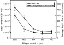
Fig. 10 presents the wear rate and the average depth of the worn tracks of the multilayered coatings. It can be found that the wear rate and the worn depth were both reduced with the decrease of the bilayer period, which was related to the decline of the frictional coefficient, as discussed before. The multilayered CrN/Cr2O3 coatings with the bilayer period of 860 nm, 590 nm and 440 nm exhibited excellent wear resistance, and the wear rates ranged from 8.1 × 10⁻⁷ mm3/(N m) to 5.4 × 10⁻⁷ mm3/(N m). Besides the surface qualities (spalling and macro-particles), the improvement of the microhardness and the adhesive strength were also the other two important reasons for the wear resistance enhancements with decreasing the bilayer period. From Fig. 10, it can also be inferred that the top Cr2O3 layer on the coating (Λ = 440 nm) has been worn out and the CrN layer was exposed, while the wear only occurred within the Cr2O3 top layer for the other four coatings (Λ = 3520 nm, 1800 nm, 860 nm and 590 nm). Compared with the coating with a bilayer period of 590 nm, the wear rate of the multilayered coating with a bilayer period of 440 nm was increased slightly, which resulted from the worn Cr2O3 top layer and the exposed CrN layer. This may be related to the relatively lower microhardness of the coating with Λ of 440 nm than that of the coating with Λ of 590 nm, which resulted in the larger contact area between the counterpart and the coating under the same normal force during the wear tests. The distensible contact area would accelerate the coating wear.
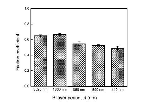 | Fig. 9 Coefficients of friction of the multilayered CrN/Cr2O3 coatings as a function of bilayer period (Λ ). |
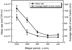 | Fig. 10 Wear rate and the average depth of the worn tracks of the multilayered CrN/Cr2O3 coatings as a function of bilayer period (Λ ). |
The morphologies of the worn tracks of the multilayered coatings are presented in Fig. 11. It can be seen that the change on the width of the worn tracks exhibited almost the similar trend as the wear rate and the average depth of the worn tracks illustrated in Fig. 10. A typical scaly morphology can be seen in the worn track of the duplex coating as shown in Fig. 11(a), which was attributed to the serious spalling of the Cr2O3 layer as discussed earlier. The flaked materials acted as a role of abrasive particles, accelerating the wear process during the wear test. In the worn track shown in Fig. 11(b), the spalling decreased significantly, but several micro-cracks were found. In Fig. 11(c-e), the spalling and the scaly morphology disappeared, and some debris was found on edges of the worn tracks. The three worn tracks were relatively smooth and presented typical furrow morphology, which was an obvious characteristic of the abrasive wear. It can also been seen that there were some pits or pinholes in the worn tracks as shown in Fig. 11(c-e), resulting from the flaking of the macro-particles as mentioned above. With more macro-particles (which also acted as a role of abrasive particles), there was more debris on the edges of the worn track presented in Fig. 11(c).
 | Fig. 11 SEM micrographs of the worn tracks of the multilayered CrN/Cr2O3 coatings with various bilayer periods (Λ ): (a) 3520 nm; (b) 1800 nm; (c) 860 nm; (d) 590 nm; (e) 440 nm. |
Combined with EDS analysis of the worn tracks illustrated in Table 2, it can be known that a small amount of Al was detected in or near the worn tracks, which came from the counterpart of alumina balls and indicated that the material transfer occurred during the wear tests. It was also noted from the data in Table 2 that some N element was found at location C, L and M as marked in Fig. 11(a) and (e), which further confirmed the CrN layers were exposed for the multilayered coating with the longest and the shortest bilayer periods. For location C, the Cr2O3 top layer was not worn out but broken down away from the CrN under-layer, resulting from the high internal stress accumulated during the long term deposition of Cr2O3 layer and the applied compressive force of the Al2O3 counterpart during the tribological test. For location L and M, the Cr2O3 top layer was worn out and the CrN below-layer was exposed, which was also confirmed by the average depth of the worn track as shown in Fig. 10. The content of N element at location L was less than 50% in the CrN phase, which might be attributed to the partial oxidation of CrN phase at the high temperature generated by the high speed friction at a local tiny region. During the tribological test, the mixed debris of CrN (partly oxidized to Cr2O3) and Cr2O3 (from the Cr2O3 top layer and partly oxidation of CrN below-layer) were pushed out by the counterpart, forming the mixed debris at location M. This might be the reason of the relatively higher N content at location L than that at location M.
| Table 2 EDS analysis of the worn tracks of the multilayered CrN/Cr2O3 coatings against Al2O3 balls |
(1)In this work, multilayered CrN/Cr2O3 coatings with hundreds of nanometers various bilayer periods were prepared by AIP technology, in which there were two kinds of interfaces: the sharp ones and the blurry ones. The CrN layers and the Cr2O3 layers crystalized well on both sides of the sharp interfaces. In the blurry interfaces, amorphous matrix and nano-crystals were found. The macro-particle density of the multilayered CrN/Cr2O3 coatings decreased gradually with decreasing the bilayer period (Λ ).
(2)With decreasing the bilayer period (Λ ), the coating hardness first increased and reached the peak value (3634 kg/mm2) at Λ of 590 nm, and then it declined again possibly due to the purity reduction of the CrN layer and Cr2O3 layer, while the adhesion was enhanced significantly and reached the maximum.
(3)The friction coefficient of the multilayered CrN/Cr2O3 coatings gradually declined from 0.67 to 0.48 with decreasing the bilayer period (Λ ). Meanwhile, the wear rate and the average depth of worn tracks also decreased slowly, which are closely related to the mechanical properties of the coating.
(4)As the bilayer period is 590 nm, the multilayered CrN/Cr2O3 coating exhibited the optimal performance, such as the highest microhardness, the strongest adhesion, and the best wear resistance.
The authors have declared that no competing interests exist.
| [1] |
|
| [2] |
|
| [3] |
|
| [4] |
|
| [5] |
|
| [6] |
|
| [7] |
|
| [8] |
|
| [9] |
|
| [10] |
|
| [11] |
|
| [12] |
|
| [13] |
|
| [14] |
|
| [15] |
|
| [16] |
|
| [17] |
|
| [18] |
|
| [19] |
|
| [20] |
|
| [21] |
|
| [22] |
|
| [23] |
|
| [24] |
|
| [25] |
|
| [26] |
|
| [27] |
|
| [28] |
|
| [29] |
|