

Evolution of the Microstructure and Strength in the Nugget Zone of Friction Stir Welded SiCp/Al–Cu–Mg Composite
[Wang D.1, 2 , Xiao B.L.1, *  , Wang Q.Z.
1 , Ma Z.Y.1 ]
, Wang Q.Z.|
|


A 6 mm-thick SiCp/2009Al composite plate was successfully joined by friction stir welding (FSW) using an ultra-hard material tool to investigate the evolution of the microstructure and the strength in the nugget zone (NZ). While some SiC particles were broken up during FSW, most of them rotated in the matrix. Large compound particles on the interfaces were broken off during FSW, whereas the amorphous layer and small compound particles remained on the interfaces. The dynamically recrystallized Al grains nucleated on the surface of fractured SiC particles during FSW, forming nano-sized grains around the SiC particles. The yield strength of the NZ decreased slightly due to the variation in the size, shape, and distribution of the SiC particles. The clean interfaces were beneficial to the load transfer between SiC particles and Al matrix and then increased the ultimate tensile strength of the NZ.
Discontinuously reinforced aluminium (DRA) matrix composites exhibit improved stiffness, strength, and wear resistance and a reduced coefficient of thermal expansion over monolithic aluminium alloys and have potential structural applications in the aerospace and automotive industries [1]. Wide industrial applications of DRA depend on effective joining methods, which are still dependent on the use of a specific material and process. The weldability of these composites is significantly reduced by the addition of ceramic reinforcements. It is hard to achieve defect-free DRA welds [2] and [3].
Friction stir welding (FSW) is a novel solid-state welding method applied particularly in the aerospace and automotive industries [1], [2], [3] and [4]. In the last few years, a number of investigations have been conducted to join DRA by FSW [5], [6], [7] and [8]. High joint efficiencies of 70%–90% could be obtained in the FSW DRA joints. Therefore, it is considered a promising welding technique for the DRA to avoid the drawbacks of fusion welding [3].
The microstructure of the FSW joints, especially the nugget zone (NZ), which suffers severe plastic deformation, changes significantly during FSW. Dynamic recrystallization (DRX) is a typical microstructure character in the NZ. For the DRA, recrystallized Al grains tend to nucleate firstly at the interface between the reinforcing particles and matrix. This would change the interfacial microstructure between the reinforcing particles and matrix. Furthermore, the size, shape, and distribution of the reinforcing particles in the NZ are also changed because the reinforcements are broken up and the sharp corners of the large particles are knocked off [7] and [9].
The variation in the microstructure affects the strength of the DRA significantly. The interface between the reinforcing particles and the matrix is one of the important factors. The excellent bond integrity of the interface improves the load transfer at the interface, thereby increasing the strength of the DRA. The interfacial microstructure depends on the characterization of the particles and matrix as well as the fabrication process of the composites [10], [11], [12], [13], [14], [15], [16] and [17]. For powder metallurgy (PM) processed SiCp/Al composites, compounds such as Al4C3 and MgAl2O4 are formed on the interface depending on the chemistry of the Al matrix [13] and [14]. Furthermore, an amorphous layer was revealed on the interface between SiC and Al diffusion bonded at 586 °C [15] and in a PM processed SiCp/6061Al composite [16].
The size, shape, and distribution of the reinforcing particles are also important for the strength of the DRA. Flom and Arsenault [18] suggested that fine reinforcement increased the yield strength (YS) of DRA. Furthermore, Liu et al. [19] reported that the long axis of the SiC particles along the tensile direction could increase the strength of DRA. The theoretical models also prove that these factors play important roles in the strength. Wu and Lavernia [20] proposed a modified shear lag model that can predict the strength of the DRA well, with the size, shape, and distribution of the reinforcing particles as the important parameters.
However, for FSW DRA, the interface between the reinforcing particles and the matrix in the NZ was rarely concerned. Feng et al. [7] found that a number of Cu2FeAl7 particles were generated on the interface between SiC and Al matrix in the NZ of FSW SiCp/2009Al composite when using a steel tool. The strength of the T4-treated composite joint was considerably lower than that of the BM (base metal) with T4 tempering (solutionized at 516 °C for 1 h, water quenched, and naturally aged for seven days). Wearing of the steel tool and the formation of interfacial intermetallics made it difficult to determine the fine interfacial microstructure in the FSW composites. The interfacial microstructure and the factors that affect the strength of the FSW composites are not clear so far. Moreover, a detailed investigation is still lacking on the variation in the size, shape, and distribution of the reinforcing particles in the NZ and their effect on the strength of the NZ.
In this study, hot-rolled SiCp/2009Al composite plate was friction stir welded using an ultra-hard cermet tool to eliminate the effect of wearing of the steel tool. The microstructural evolution in the NZ and interfacial fine microstructures in both as-rolled and as-FSW composites were examined in detail. The aims were (a) to elucidate the evolution of the SiC particles and the interfacial microstructure between the SiC particles and Al matrix during FSW and (b) to investigate the factors that affect the strength of the NZ.
6 mm-thick 15 vol.% SiCp/2009Al composite plates were used in this study. The composite was produced by a PM technique, in which 50 μm 2009Al powder and 7 μm SiC powder were blended and hot consolidated at 580 °C. After hot rolling at 480 °C, the composite plates were subjected to T4 tempering (solutionized at 516 °C for 1 h, water quenched, and naturally aged for seven days). The plates were friction stir butt welded along the rolling direction at a welding speed of 100 mm/min and a tool rotation rate of 800 r/min. An ultra-hard cermet tool with a shoulder 20 mm in diameter and a conical pin 8 mm in diameter and 5.8 mm in length was used. After welding, the FSW sample was naturally aged for seven days. Furthermore, part of the FSW sample was re-treated to a T4 temper. The NZ of the as-FSW joint and T4-treated joint were named as as-FSW and FSW-T4, respectively.
The joint was cross-sectioned perpendicular to the welding direction for examination by optical microscopy (OM) and scanning electron microscopy (SEM, Quanta 600). The OM specimen was mechanically polished and etched by Keller's reagent. The interfaces between the SiC and Al matrix were analysed by transmission electron microscopy (TEM, Tecnai G2 20) and high resolution TEM (HREM, Tecnai F20). Thin foils for TEM were thinned by ion milling.
Tensile specimens with a gauge length of 5 mm and width of 1.4 mm were machined perpendicular to the welding direction, with the gauge length completely within the NZ. The tensile direction of the BM specimens was perpendicular to the rolling direction. Tensile tests were conducted using an Instron 5848 micro-tester at a strain rate of 1 × 10⁻³ s-1. The property data for each condition were obtained by averaging three test results. The fracture surfaces of the tensile specimens were observed using SEM.
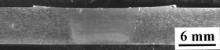
Fig. 1 shows a cross-sectional macrograph of the FSW SiCp/2009Al joint. No defects were detected in the joint, indicating that a sound joint could be achieved by FSW using ultra-hard cermet tools. Similar to those in the other FSW DRA joints [7], the NZ in the present FSW SiCp/2009Al joint exhibited a basin shape. However, unlike in previous reports using steel tools [7], no onion structure was observed in the NZ in this study.
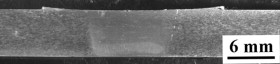 | Fig. 1. Optical macrograph showing cross-section of FSW SiCp/2009Al composite. |
Fig. 2(a) shows the OM image of the SiCp/2009Al composite perpendicular to the rolling direction. The equiaxed grains of the Al matrix were ∼10 μm in size. For the as-FSW sample, the Al matrix in the NZ was characterized by fine equiaxed recrystallized grains of ∼6 μm in size, smaller than those in the BM sample. Furthermore, the edges and corners of some SiC particles became blunt in the NZ, due to the abrasion during welding ( Fig. 2(b)). The grain size of the FSW-T4 sample ( Fig. 2(c)) was similar to that of the as-FSW sample. This indicated that the growth of the Al grains would be inhibited by the SiC particles in the heat treatment process.
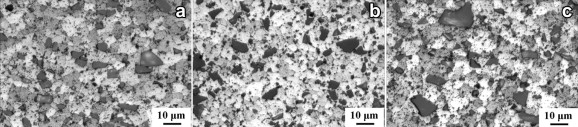 | Fig. 2. Optical micrographs of SiCp/2009Al composite: (a) BM, (b) as-FSW sample, (c) FSW-T4 sample. |
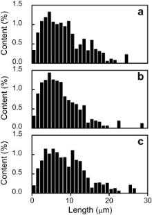
Fig. 3 shows the results of quantitative measurements of the particle size distribution in the BM and the as-FSW sample. For the BM, the size diversity of the SiC particles was observed along the rolling and transverse directions, because the long axis of the SiC particles tended to be distributed along the rolling direction. The sizes of SiC particles in the as-FSW sample, the BM along the rolling direction, and the BM along the transverse direction were estimated to be 8.4, 9.0, and 7.5 μm, respectively. For the as-FSW sample, the size of the SiC particles was approximately the average value of the BM in the two directions. Furthermore, the fraction of SiC particles larger than 8.5 μm was higher than that of the BM along the transverse direction. Moreover, the average aspect ratios of the BM and the as-FSW samples were 1.7 and 1.5, respectively. These implied that part of the SiC particles flowed and rotated in the matrix with the stirring of the welding tool and some large SiC particles were broken up during FSW.
 | Fig. 3. Quantitative measurements of the particle size distribution: (a) as-FSW sample, (b) BM perpendicular to the rolling direction, (c) BM along the rolling direction. |
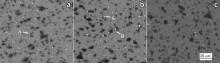
Fig. 4(a) illustrates the backscattered electron (BSE) image of the BM. Some circular white particles were observed in the matrix (marked as “A”). EDS (energy dispersive spectroscopy) analyses indicated that the particles contained 88.2 Al, 7.84 Cu, 1.57 Si, 1.68 Mg, and 0.73 Fe (at.%). The Fe element was introduced into the matrix in the fabrication process of the BM, forming the Al7Cu2Fe intermetallic compounds. In the hot rolling and subsequent cooling processes, the Al2Cu phase nucleated on the Al7Cu2Fe particles and grew up [21] and [22]. When the sample was solutionized, most of the Al2Cu phases were dissolved into the matrix. However, part of the Al2Cu phases around the Al7Cu2Fe phases remained in the heat treatment process. Therefore, circular white particles were detected in the matrix.
 | Fig. 4. Backscattered electron image of SiCp/2009Al composite: (a) BM, (b) as-FSW, (c) FSW-T4. |
Fig. 4(b) shows the BSE image of the as-FSW sample. There were also some white particles in the matrix. EDS analyses indicated that the irregular particles (marked as “B”) contained 87.7 Al, 7.6 Cu, 2.6 Si, 1.4 Mg, and 0.7 Fe (at.%), and the circular particles (marked “C”) contained 80.0 Al, 24.2 Cu, 3.1 Si, and 1.7 Mg (at.%).
Jariyaboon et al. [23] measured the peak temperature distribution during FSW of 2024Al-T351 alloy. They found that the temperatures adjacent to the NZ were 480 °C. Mahoney et al. [24] reported that the temperature adjacent to the NZ was measured as 420–470 °C during FSW of 7075Al-T651 alloy. For the SiCp/2009Al composite, the peak temperature of the NZ during FSW was possibly similar to the above temperature. After welding, when the sample was cooled to room temperature, the Al2Cu phases would precipitate in the as-FSW sample and then form the circular particles (marked as “C”) and the fine white phases. Moreover, the Al2Cu phases would also nucleate and grow on the Al7Cu2Fe phases. Finally, the irregular particles (marked as “B”) were formed.
For the FSW-T4 sample ( Fig. 4(c)), the number of white particles clearly decreased. The shape of the remaining particles was basically circular and the irregular particles almost disappeared. EDS results suggested that most of the particles contained Fe element. After the solution treatment, most of the Al2Cu phases were dissolved. However, some Al2Cu phases around the Al7Cu2Fe particles remained and formed the circular particles in the matrix, similar to those in the BM sample.
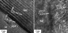
Fig. 5(a) shows a typical TEM image of large compounds on the interfaces between SiC particles and Al matrix in the BM. EDS analyses indicated that the phase contained 20.4 Al, 9.7 Cu, 33.2 Si, 4.2 Mg, 26.8 C, 5.8 O (at.%, marked as “D”). It was reported that impurities such as Si and oxide, adhering on the surface of original SiC particles, could react with Al, Mg, and Cu elements during the fabrication process [25] and [26]. Typical phases of Al4C3, MgAl2O4, and Mg2Si formed on the interfaces. Furthermore, Al2Cu phases could nucleate and grow on these compounds. Therefore, complex compounds would form on the interfaces. However, for some SiC particles, there were few impurities on the original surfaces. Therefore, a relatively clean interface with few small compounds was observed, as shown in Fig. 5(b).
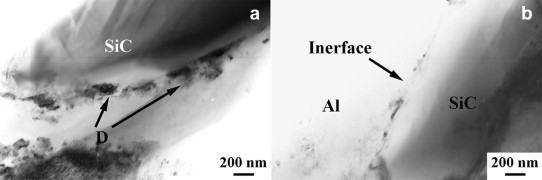 | Fig. 5. TEM micrographs of T4-treated SiCp/2009Al composite showing: (a) large compounds and (b) small compounds on SiC/Al interfaces. |
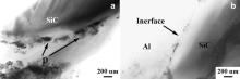
Fig. 6(a) shows a typical TEM image of the interfaces between SiC and Al matrix in the as-FSW sample. Some large compound particles were observed in the matrix around the SiC particles (marked as “E”). EDS analyses indicated that the particles contained 9.73 Al, 0.66 Cu, 27.5 Si, 25.6 Mg, 12.9 C, and 23.7 O (at.%). This indicates that the large compounds on the interfaces in the BM, as shown in Fig. 5(a), were broken off and dispersed into the matrix adjacent to the SiC particles during FSW. Therefore, most of the SiC/Al interfaces became clean after FSW.
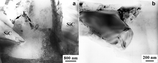 | Fig. 6. TEM micrographs of as-FSW SiCp/2009Al composite showing: (a) large compounds broken off from interface and (b) fractured small SiC particles with clean interface. |
Fig. 6(b) shows the existence of a few fine SiC particles with relatively clean interfaces in the as-FSW sample. Such fine particles are believed to result from the knocking-off of sharp corners and edges of large SiC particles in the FSW process. Feng et al. [7] and Root et al. [8] reported similar phenomena in FSW SiCp/2009Al and Al2O3/7005Al composites. The new interfaces formed by the broken SiC were very clean without any compounds.
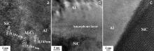
Fig. 7 shows the HREM images of the interfaces in the BM. There were three kinds of interfacial microstructures between the SiC particles and Al matrix. For the first kind, some small compounds formed on the surface of SiC particles and they were identified as Al4C3 phase with a crystallographic orientation relationship of ( Fig. 7(a)). However, the Al4C3 had no crystallographic orientation relationships with the Al matrix. For the second kind of interface, an amorphous layer was present on the interfaces between the SiC particles and Al matrix ( Fig. 7(b)). There were no crystallographic orientation relationships between the SiC particles and Al matrix on the two sides of the amorphous layer. A similar interfacial structure in the PM DRA was also reported by other researchers [12] and [16]. The third kind of interface is shown in Fig. 7(c). There were no reaction products or amorphous layer on the interface. However, no preferential crystallographic orientation relationship was observed between SiC particles and Al matrix.
 | Fig. 7. HREM micrographs of T4-treated SiCp/2009Al composite showing SiC/Al interfaces: (a) with compounds, (b) with amorphous layer, and (c) without crystalline relationship. |
For the typical interfacial microstructure between the unbroken SiC particles and Al matrix in the as-FSW sample, a small Al4C3 particle was detected on the surface of SiC particles ( Fig. 8(a)). It had a crystallographic orientation relationship with the SiC particle,. No other large compounds were observed on the interfaces. In other places on the interfaces, the SiC particle did not have an orientation relationship with the Al matrix. Furthermore, the amorphous layers in the BM, as shown in Fig. 7(b), were also observed on some interfaces in the NZ (not shown). Fig. 8(b) shows an HREM image of a typical interfacial microstructure between the broken SiC particles and Al matrix. An Al grain several nanometres in size was observed near a SiC particle and had a crystallographic orientation relationship with the SiC particle, i.e. (marked by the white curve). This means that the Al matrix nucleated on the surface of fractured SiC particles in the DRX process.
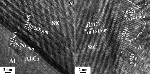 | Fig. 8. HREM micrographs of as-FSW SiCp/2009Al composite showing: (a) small Al4C3 particle on SiC/Al interface and (b) crystallographic relationship between SiC and Al. |
shows the strength of the as-FSW sample and FSW-T4 sample. For comparison, the strength of the BM is also listed. The yield strength (YS) and ultimate tensile strength (UTS) of the as-FSW sample were lower than those of the BM, since the precipitates coarsened during the thermo-mechanical cycle of the FSW process (shown in Fig. 4(b)). Meanwhile, the precipitation of the coarse Al2Cu phases in the Al matrix resulted in some solute-free regions near the interface between the SiC and matrix, where the voids were prone to nucleate and grow near the interface during tensile process [27]. Therefore, the elongation of the as-FSW sample decreased compared to that of the BM. In the FSW-T4 sample, the YS decreased slightly compared to that of the BM sample; however, the UTS of the FSW-T4 sample increased by 22 MPa. The elongation of the FSW-T4 sample also increased slightly compared to that of the BM. This will be discussed below in detail.
| Table 1. Tensile property of SiCp/2009Al composites |
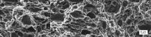
Fig. 9(a) presents a typical tensile fracture surface of the BM sample. The fracture surface was characterized by dimples, showing the characteristic of ductile fracture, and fractured SiC particles. Similar to the previous result [7], the surfaces of the SiC particles were smooth, indicating that the SiC particles were broken up in the tensile process. In the as-FSW sample ( Fig. 9(b)), the fracture surface was similar to that of the BM sample. Although the strength of the as-FSW sample was lower than that of the BM sample, particle fracture was also the dominant damage mode. A similar result was reported by Pandey et al. [27]. In the FSW-T4 sample ( Fig. 9(c)), the fracture surface was similar to that of the BM sample.
 | Fig. 9. SEM images of fracture surface of SiCp/2009Al composite: (a) BM, (b) as-FSW, (c) FSW-T4. |
During the FSW process, the material in the NZ underwent a severe plastic deformation at high temperatures. When the material was stirred, some of SiC particles made direct contact with the welding tool. Therefore, the compounds on the interfaces were broken off directly due to the interaction between the welding tool and SiC particles. Moreover, the SiC particles, driven by the flowing of the Al matrix during the severe plastic deformation process, moved in the matrix. When the driving stress was high enough, it was likely that the compounds on the interfaces fell off the SiC particles. Therefore, some large compound particles with complex compositions were observed in the matrix adjacent to the SiC particles.
Although the SiC particles did not have a preferential crystallographic orientation relationship with the Al matrix in the BM, effective bonding formed during the fabrication of the composite. Similar to the hot deformation process of the BM, when the SiC particles rotated in the matrix during FSW, the Al adjacent to SiC particles would synergistically deform with the SiC particles. Therefore, for small compounds such as Al4C3 that have a high bonding strength with SiC due to chemical reaction, the crystallographic orientation relationship was retained. The amorphous layers between SiC and Al with a chemical bond also had sufficiently high bonding strength to avoid breaking off.
During FSW, the tool broke up some large SiC particles or blunted the sharp corners of the SiC particles, as shown in Fig. 2 and Fig. 6. As discussed in Section 3, the peak temperature of the NZ was lower than that of the hot consolidated temperature significantly. Furthermore, the duration of FSW at high temperatures was very short [23] and [24]. Therefore, it is not likely to form compounds on the new surface of the fractured SiC particles, and the very clean interfaces formed after FSW. However, the new surfaces of the fractured SiC particles made direct contact with the Al matrix with high deformation energy in the welding process. In this case, the Al matrix was prone to nucleating on the SiC particles and forming a crystallographic orientation relationship to reduce the free energy of the interfaces.
Similar results were reported by Vandenburg and Dehosson [17], who observed a preferential crystallographic orientation relationship between SiC and Al when the composite was produced by cold isostatic pressing and subsequent extrusion. This means that the Al grains could nucleate on the SiC surface if SiC and Al made contact without pre-bonding and then underwent an intense plastic deformation. For the FSW process, the plastic deformation was severe within a very short duration. In this case, the Al matrix could nucleate on the surface of the fractured SiC particles, even though the fractured surface of SiC was in high index orientation. Moreover, the cooling rate of FSW was very fast. Thus, the growth of the recrystallized grains on the SiC particles was limited. The nano-scaled grains were formed on the interface.
The strength of the SiCp/2009Al composite was greatly dependent on the precipitates in the Al matrix. During FSW, many coarse Al2Cu phases were formed in the NZ, as shown in Fig. 3(b). Therefore, the strength of the as-FSW sample decreased significantly compared to that of the BM sample. For the FSW-T4 sample, similar to the BM sample, most of the coarse Al2Cu phases were dissolved in the matrix and then precipitated as the GP zones during the natural ageing process. However, the YS of this sample was reduced by 12 MPa and the UTS was increased by 22 MPa compared to those of the BM.
Besides the precipitations, the size, shape, and distribution of the reinforcing particles were also important factors affecting the strength of the DRA. As discussed in Section 3, the aspect ratio and average size of the SiC particles in the as-FSW samples changed compared to those of the BM sample. Moreover, heat treatment would not affect the SiC particles in the sample. Therefore, the variation of the SiC particles in the FSW-T4 sample would change the strength of this sample.
Many researchers have attempted to predict the strength of DRA using different models. Wu and Lavernia [20] proposed a modified shear lag model to predict the strength of the DRA and achieved values similar to the experimental results. Liu et al. [28] also used this model to predict the YS and UTS of SiCp/2009Al composites. To calculate the strength using this model, the DRA was divided into three zones: the particle, plastic, and elastic zones. The YS of the DRA, σy could be calculated by:
The details of this model can be found in previous reports [20] and [28]. The YS of the 2009Al, which was fabricated by the same PM process, was 271 MPa. The calculated YS of the BM was 345 MPa, similar to the experimental value (343 MPa). This indicates that this model is appropriate for this DRA. The aspect ratio and average size of the particles in the NZ were 1.5 and 8.4 μm, respectively, as presented in Section 3, and were therefore different from those in the BM. Therefore, the calculated YS was 339 MPa for the FSW-T4 sample, similar to the experimental value (331 MPa). The variation in the shape and size of the SiC particles was the main factor that decreased the YS of the NZ for the FSW-T4 sample.
For the UTS, some other mechanisms took place. In the FSW-T4 sample, the coarse intermetallic compounds on the interface between the SiC and the Al matrix were broken off. The clean interface was beneficial to the load transfer between the SiC particles and the Al matrix [29]. Furthermore, the Al nucleated on the fractured surface of SiC particles. Good metallurgical bonding would improve the load transfer on the interface as well as dislocation–particles and dislocation–dislocation interaction. Finally, the UTS of the sample increased. In addition, it was reported that the interface with an excellent metallurgical bonding could result in the lattice rotation of the matrix around the interface during deformation [30]. During the tensile process, the Al grains around the SiC particles would deform compatibly with the grains in the matrix. Therefore, the elongation of the FSW-T4 sample was improved slightly compared to that of the BM sample.
(1) Defect-free FSW joints of 6 mm hot-rolled SiCp/2009Al composite plate were successfully achieved using an ultra-hard material tool.
(2) The size and shape of SiC particles in the NZ changed because the particles were broken up and rotated during the severe plastic deformation process of FSW.
(3) During FSW, the large compound particles on the interfaces between SiC and Al matrix fell off, whereas the small compound particles and amorphous layers on the interfaces were unchanged.
(4) The dynamically recrystallized grains nucleated on the surface of broken SiC particles to reduce the free energy of the interfaces and formed nano-sized grains. A crystallographic orientation relationship between broken SiC particles and Al matrix,, was observed.
(5) The YS of the FSW-T4 sample decreased slightly due to the variation in the size, shape, and distribution of the SiC particles. The clean interface between SiC particles and Al matrix improved the load transfer and then raised the UTS of the FSW-T4 sample.
The authors gratefully acknowledge the support of the National Basic Research Program of China (No. ).
| 1. |
|
| 2. |
|
| 3. |
|
| 4. |
|
| 5. |
|
| 6. |
|
| 7. |
|
| 8. |
|
| 9. |
|
| 10. |
|
| 11. |
|
| 12. |
|
| 13. |
|
| 14. |
|
| 15. |
|
| 16. |
|
| 17. |
|
| 18. |
|
| 19. |
|
| 20. |
|
| 21. |
|
| 22. |
|
| 23. |
|
| 24. |
|
| 25. |
|
| 26. |
|
| 27. |
|
| 28. |
|
| 29. |
|
| 30. |
|