


Microstructure Evolution and Tensile Properties of Ti3Al/Ni-based Superalloy Welded Joint
[Chen Bingqing, Xiong Huaping*  , Sun Bingbing, Tang Siyi, Guo Shaoqing, Zhang Xuejun]
, Sun Bingbing, Tang Siyi, Guo Shaoqing, Zhang Xuejun]
|
|


In the present work, the dissimilar joining of a Ti3Al-based alloy to a Ni-based superalloy was attempted by gas tungsten arc (GTA) welding technology. Sound joints were successfully achieved by using a Cu–Ni alloy as filler material. According to X-ray energy dispersive spectroscopy and X-ray diffraction analysis results three transitional layers at the weld/Ti3Al interface were verified as follows: Ti2AlNb phase dissolved with Cu and Ni; Al(Cu, Ni)2Ti, (Cu, Ni)2Ti and (Nb, Ti) solid solution; Cu-rich phase and a complex multi-element phase. The In718/weld interface is characterized by solid solutions of Ni, Cu, Cr, Fe and Nb. The average tensile strength of the as-welded joints at room temperature is 163 MPa, and after a post–weld heat treatment it is increased slightly to 177 MPa. The fracture occurred at the surfacial layer of the joined Ti3Al base alloy, indicating that the Ti2AlNb layer dissolved with Cu and Ni is the weak link of the Ti3Al/In718 joint.
In recent years, Ti3Al-based alloy is arising as one of the most attractive structural materials for applications in aerospace industry due to its low density, superior strength, high stiffness and good mechanical properties as well as oxidation resistance at elevated temperatures [1] and [2]. Utilizing the advantages over conventional materials currently in use, e.g., Ni-based superalloy and Ti-based alloy, Ti3Al has become the potential material for the production of components in aerospace engines or heat resistance parts in guided missiles. Especially, substituting Ti3Al-based alloy for Ni-based superalloy can significantly enhance the thrust-weight ratio of aeroengines and increase their performances [3] and [4].
Apparently, developing welding and joining technologies of Ti3Al to itself and to other materials is of great importance for the successful applications of this material. And due to the increasing demand for weight reduction of aeroengines, the dissimilar joining of Ti3Al-based alloy to Ni-based superalloy, which indicates high-temperature service potential, should be very attractive for engineering applications.
However, it is known that the hot workability of Ti3Al-based alloy is not so good and the material presents poor weldability. It usually shows a tendency to crack during cooling (solid-state cracking) when subjected to welding processes [5]. In the past decades, efforts have been made to join Ti3Al by fusion welding [5] and [6], brazing [7]as well as solid-state joining processes [8] and some advances have been achieved [9]. For example, in the research by Wu et al., using laser beam welding technology, the room-temperature tensile strength of the Ti3Al joint was equal to that of the base material [3] and in another report, the strength value at 923 K of the laser welded Ti3Al joint could reach about 733 MPa [10]. The joining of Ti–22Al–25Nb and TC11 alloys was carried out using electron beam welding technique and the room-temperature tensile strength of the joint was higher than that of the TC11 base alloy [11]. However, these researches were mainly focused on joining of Ti3Al to itself and to Ti-based alloy. Concerning the joining of Ti3Al to Ni-based superalloy, few studies have been published so far.
Considering the quite different chemical compositions and thermo-physical properties of Ti3Al-based alloy and Ni-based superalloy, joining these two materials is a great challenge. For example, the dissolution enthalpy of Ti in liquid Ni solvent is -170 kJ/mol [12], indicating the high affinity of the two elements. They could react and solidify as kinds of Ti–Ni intermetallics such as Ti2Ni, TiNi and TiNi3according to the Ti–Ni binary alloy phase diagram [13]. Therefore the primary problem of the dissimilar joining of Ti3Al to Ni-based superalloy is the strong tendency of the formation of brittle phases at the joining interface, which would bring great difficulties to the welding metallurgy and deteriorate the mechanical properties of the joints [14]. Furthermore, the considerable differences in thermal expansion coefficient, melting temperature and thermal conductivity between these two materials make the welding conditions be more complicated [15] and [16]. It is thus extremely difficult to achieve a strong joining between Ti3Al-based alloy and Ni-based superalloy. Chen et al. made an attempt to join a Ti3Al-based alloy to a Ni-based superalloy using a Ti–Zr–Cu–Ni filler alloy, micro-cracks were visible within the dissimilar joints and the corresponding joint strength was only 86.4 MPa [17].
This study made an attempt to join a Ti3Al-based alloy to a Ni-based superalloy by gas tungsten arc (GTA) welding technology using a Cu–Ni alloy as filler material. At least, it is well known that the Cu–Ni solid solution alloy is metallurgically compatible with the Ni-based superalloy, and its superior ductility as well as good fluidity in liquid form is favorable to plastic deformation and residual stress relieving of the joint. The metallurgical behaviors within the joint were investigated, and the microstructure evolution across the dissimilar joint was characterized and correlated with mechanical properties.
The Ti3Al-based alloy used for GTA welding is Ti–24Al–15Nb–1Mo (at.%) composed of α2+ O (Ti2AlNb) + B2 three phase equiaxial grains [18] and the Ni-based superalloy to be joined in this study is Inconel 718 (In718), whose chemical composition is given in Table 1. Rectangular plates of 2.5 mm in thickness, 45 mm in width and 75 mm in length were machined from the base materials and cleaned for welding experiments. The filler material is a Cu–Ni solid solution alloy (CuNi18–22) and its cross-section geometry is 2 mm × 2 mm. In this experiment, pure Cu and pure Ni metals were also used as filler materials for comparison.
| Table 1. Chemical composition of the In718 base alloy (wt%) |
After being preheated to 573 K in an air heat treatment furnace, the base alloys were GTA welded with a welding speed of 80–100 mm/min, a voltage of 12–15 V and a current of 50–60 A DC. Flowing argon shielding was applied to the weld bead during the welding process with flow rates as follows: 15 L/min for the top, 20 L/min for the tail and 8 L/min for the bottom surfaces, respectively. Two kinds of samples were prepared: as-welded sample, which was subjected to furnace cooling after welding from 573 K to room temperature; post-weld heat treated sample, which was annealed at 973 K for 1 h after welding and then furnace cooled. The cooling rates of both the processes were 0.02–0.05 K/s.
The as-welded and post-weld heat treated samples were sectioned transversely to the welding direction. Microstructure and chemical composition examinations along the cross sections of the dissimilar joints were carried out by scanning electron microscopy (SEM; CS-3400) equipped with an X-ray energy dispersive spectroscopy (XEDS) system. Transverse tensile tests were conducted to evaluate the tensile strength of the joints at room temperature. The fractured surface of the joint was inspected by SEM, XEDS and X-ray diffraction (XRD). Furthermore, the fractured surfaces of the joint at the weld side were polished layer by layer and examined by XRD to verify the phase constitution of the weld/Ti3Al interface.
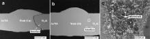
To investigate the individual metallurgical effects of Cu and Ni, GTA welding of the Ti3Al and In718 base alloys were conducted using pure Cu and pure Ni as filler metals in the first place. The back-scattered electron images (BSEIs) of the cross sections of the joints are presented in Fig. 1. In the joint welded with pure Cu filler metal, a macrocrack was visible along the interface between the weld and Ti3Al base alloy after welding, as shown in Fig. 1(a). The thermal expansion coefficients of Cu, Ni, the Cu–Ni filler alloy, the Ti3Al and In718 base alloys used in this study are ~17.5, ~13.0, ~13.5, ~9.1 and ~13.0 (× 10-6K-1), respectively. Obviously, the considerable difference of thermal expansion coefficients between Cu and Ti3Al was a problem when using pure Cu as filler metal, resulting in high residual stress at the joint interface [19]. For the joint welded with pure Ni filler metal, no obvious defect is observed in Fig. 1(b), but it is seen in Fig. 1(c) that microcracks exist at the weld/Ti3Al interface. And the average room-temperature tensile strength of the joints welded with Ni was tested to be only 17 MPa. It is concluded that in this work, using pure Cu and pure Ni as filler metals, the Ti3Al-based alloy and Ni-based superalloy cannot be successfully joined together.
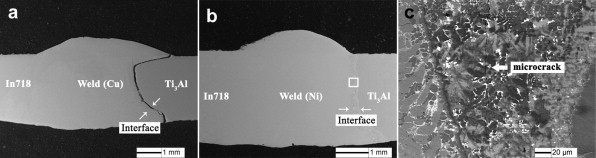 | Fig. 1. BSEIs of the cross sections of the Ti3Al/In718 joints welded with (a) Cu filler metal and (b) Ni filler metal. (c) Magnification image of the region marked by a white square in (b). |
3.2.1. As-welded joint
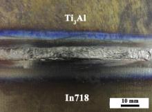
The Cu–Ni alloy was then adopted as filler material. Fig. 2 shows the top-view photograph of the dissimilar GTA welded sample using the Cu–Ni filler alloy. It is seen that the joint has a relatively uniform weld bead without common weld defects such as hot cracking, undercutting, lack of fusion, and so on.
 | Fig. 2. Top-view photograph of the dissimilar GTA welded sample using the Cu–Ni filler alloy. |
The BSEI of the cross section of as-welded joint is exhibited in Fig. 3(a). A sound joint of the Ti3Al and In718 alloys has been obtained and the Cu–Ni filler alloy penetrated well into the base materials. The interfaces between the weld and base alloys are clearly observed.
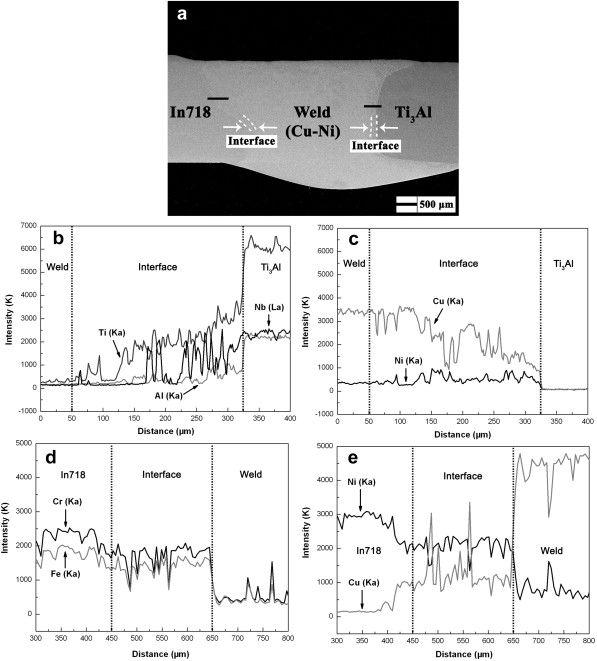 | Fig. 3. (a) BSEI of the cross section of the Ti3Al/In718 joint welded with the Cu–Ni filler alloy. Distribution profiles of major elements across the weld/Ti3Al interface (b, c) and the In718/weld interface (d, e). |
The XEDS line scanning analysis results along the black lines in Fig. 3(a) are displayed in Fig. 3(b)–(e), which show the distribution profiles of major elements across the weld/Ti3Al and In718/weld interfaces, respectively. It is shown in Fig. 3(b) and (c) that at the weld/Ti3Al interface, Ti, Al and Nb decrease gradually from the Ti3Al side to the weld and the variation trend of Cu is the opposite. The concentration level of the Ni element remains the same at the interface as that in the weld and decreases when reaching the Ti3Al base alloy. It is noted that at the weld/Ti3Al interface, the concentrations of the major elements exhibit a relatively steep change, indicating that the dissimilar metal liquids were not mixed so uniformly in this region [20]. In contrast, the concentration profiles of Fe, Cr, Ni and Cu across the In718/weld interface, as shown in Fig. 3(d) and (e), present approximately uniform distribution.
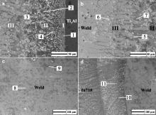
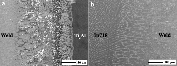
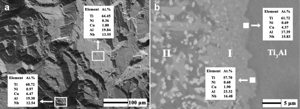
Microstructure evolution along the cross section of the as-welded Ti3Al/In718 joint is presented in Fig. 4. At the weld/Ti3Al interface, a clear reaction region composed of three characteristic layers is observed and the layers are specified by Roman numerals I–III in Fig. 4(a) and (b). The XEDS analysis was directed at clarifying the phase constitutions and the corresponding results are presented in Table 2.
 | Fig. 4. Microstructure evolution along the cross section of as-welded Ti3Al/In718 joint: (a) weld/Ti3Al interface close to the Ti3Al base alloy, (b) weld/Ti3Al interface close to the weld, (c) weld and (d) In718/weld interface. |
| Table 2. Chemical compositions of the phases in the Ti3Al/In718 joint welded with the Cu–Ni filler alloy and the corresponding deduced phases |
The layers observed at the weld/Ti3Al interface are as follows:
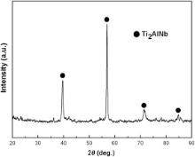
I. The layer adjacent to the Ti3Al base material (5–15 μm) mainly consists of crystals showing light gray contrast (labeled “1” in Fig. 4(a)), which are identified to be Ti2AlNb phase dissolved with Cu and Ni from the XEDS analysis results, as presented in Table 2. This layer was formed due to the diffusion of elements Cu and Ni from the filler alloy into the surface layer of the Ti3Al base material. Bright precipitated particles distributed in the gray matrix are also observed in this layer.
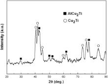
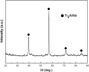
II. This reaction layer is composed of various intermetallic compounds (∼100 μm). During the welding process, elements from the filler and Ti3Al base alloys reacted in this layer and new phases were generated. From the XEDS analysis results and the Al–Cu–Ti ternary alloy phase diagram [21], the dark phase (labeled “2” in Fig. 4(a)) is assumed to be Al(Cu, Ni)2Ti intermetallics and the gray one is deduced to be (Cu, Ni)2Ti (labeled “3” in Fig. 4(a)). In order to verify the phase constitution of this layer, the fractured surface of the joint subjected to the tensile test (see section below) at the weld side was polished off 5–10 μm and then analyzed by XRD. The peaks corresponding to the AlCu2Ti and Cu2Ti compounds are detected in the XRD pattern of this layer shown in Fig. 5.
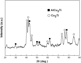 | Fig. 5. XRD pattern of Layer II at the weld/Ti3Al interface. |
These reaction products have been observed previously in the brazed joints of TiAl intermetallics. For example, Lee et al. classified TiCu2and Ti(Cu, Ni) as the major phases near the fracture surfaces of infrared brazed γ-TiAl joints [22], Zhou et al. reported the formation of Al(Ni, Cu)2Ti in the joint between TiAl and a Ni-based superalloy when using Cu foil and Cu–Ti alloy as interlayers [23] and Tetsui pointed out that AlM2Ti type hard B2 intermetallics was formed inside the brazed joints and at the boundaries to TiAl as a result of reactions of TiAl with Cu, Ni or Au from the brazing filler [24] and [25]. According to the Al–Cu–Ti ternary alloy phase diagram [20]there is an eutectic reaction at 1293 K which is L = AlCu2Ti + (Cu) and a transition reaction at 1173 K which is L + (Cu) = AlCu2Ti + Cu2Ti. So the formation of Al(Cu, Ni)2Ti and (Cu, Ni)2Ti phases at the weld/Ti3Al interface in this study is reasonable. The bright precipitates in Layer I and II are deduced to be (Nb, Ti) solid solutions (labeled “4” in Fig. 4(a)), dissolved with Cu and Al.
III. The layer next to the weld (170–180 μm) with relatively slow cooling rate in this region consists of coarse dendritic crystals which are mainly a Cu-rich phase (labeled “5” in Fig. 4(b)) as adjacent to the Cu–Ni filler alloy. Block-shape precipitates showing white contrast are also observed and considered to be a complex multi-element phase according to the XEDS analysis results (labeled “6” in Fig. 4(b)). The phase with small grain size close to Layer II is identified as Cu-rich phase dissolved with Ti, Ni and Al (labeled “7” in Fig. 4(b)).
Fig. 4(c) displays the microstructure of the weld zone, which is mainly (Cu, Ni) solid solution (labeled “8” in Fig. 4(c)). Embedded in the gray matrix, there are some needle-like crystals that are also (Cu, Ni) solid solution, but dissolved with Fe and Cr (labeled “9” in Fig. 4(c)). Additionally, it is evident from the XEDS analysis results that the In718/weld interface is mainly composed of solid solutions of four or five elements of Ni, Cu, Cr, Fe and Nb, showing complicated feature.
3.2.2. Post-weld heat treated joint
The cross section of the post-weld heat treated sample was also examined by SEM and XEDS. After the annealing treatment, the microstructure of the joint stays the same as that of the as-welded one as shown in Fig. 6. The weld/Ti3Al interface still contains three transitional layers and the In718/weld interface exhibits coarse feature. Based on the XEDS results, the phase constitutions of the weld/Ti3Al interface from the Ti3Al side to the weld are: Ti2AlNb dissolved with Cu and Ni, Al(Cu, Ni)2Ti, Ti(Ni, Cu, Al, Nb) solid solution, Cu-rich phase, (Cu, Ni)2Ti and a complex multi-element phase. The weld comprises (Cu, Ni) solid solutions and the In718/weld interface consists of Ni solid solutions dissolved with Cu, Fe, Cr and Nb.
 | Fig. 6. Microstructure evolution along the cross section of the post-weld heat treated Ti3Al/In718 joint using the Cu–Ni filler alloy: (a) weld/Ti3Al interface and (b) In718/weld interface. |
Transverse tensile tests were conducted at room temperature for the dissimilar Ti3Al/In718 joints welded with the Cu–Ni filler alloy. The strength values of the as-welded and post-weld heat treated joints are listed in Table 3. The average room-temperature tensile strength of the as-welded joint is calculated to be 163 MPa and the value for the post-weld heat treated one is 177 MPa. During welding, introducing the Cu–Ni filler alloy into the weld restrained the interreaction between the Ti3Al and In718 base alloys and thus effectively decreased the tendency of the formation of interfacial brittle phases. As a consequence, the feasibility of dissimilar joining of Ti3Al-based alloy and Ni-based superalloy using GTA welding technology has been verified in our experimental study.
| Table 3. Room-temperature tensile strength of the Ti3Al/In718 joints welded with the Cu–Ni filler alloy |
After the annealing treatment, the tensile strength of the Ti3Al/In718 joint shows a slight increase. The annealing treatment helped releasing the residual stress in the joint generated during welding to a certain extent and contributed to the improved tensile properties.
From the macroscopic observation of the fractured samples after the tensile tests, the fractures monotonously occurred at the weld/Ti3Al interfaces. The fractured surface morphology of the as-welded Ti3Al/In718 joint is presented in Fig. 7(a) and a typical brittle rupture is observed characterized by cleavage facets. According to the XEDS analysis results listed in Fig. 7(a), the chemical composition of the fractured surface is very close to that of the Ti3Al base alloy but dissolved with a little Cu and Ni. However, the Cu and Ni contents in the fracture are less than those of Layer I in Fig. 4(a). It is thus deduced that the fracture occurred somewhere at the boundary between Layer I and the Ti3Al base alloy. And in the XRD pattern of the fractured surface shown in Fig. 8, the peak corresponding to Ti2AlNb has been detected. It should be noted that this Ti2AlNb phase detected here has been dissolved with Cu and Ni. In order to investigate the specific position that the facture actually took place, the Layer I/Ti3Al boundary was inspected again by SEM and XEDS, as shown in Fig. 7(b). Apparently, according to the XEDS analysis results there exists a 2–3 μm thick diffusion reaction layer at the surface of the joined Ti3Al base alloy, dissolved with several percentages of Cu and a small amount of Ni. It is noticeable that the chemical composition of this surfacial layer marked by white solid squares in Fig. 7(b) is almost identical to those listed in Fig. 7(a). This demonstrates that the fractured position lies in this thin surfacial layer of the joined Ti3Al base alloy and it just corresponds to the weak link of the Ti3Al/In718 joint welded with the Cu–Ni filler alloy. Subsequent work should be carried out to further improve the microstructure and mechanical properties of the dissimilar joint of Ti3Al-based alloy and Ni-based superalloy [26].
 | Fig. 7. (a) Morphology of fractured surface of the Ti3Al/In718 joint welded with the Cu–Ni filler alloy; (b) high magnification BSEI of the Layer I/Ti3Al boundary. |
 | Fig. 8. XRD pattern of the fractured surface of the joint at the Ti3Al side. |
A Ti3Al-based alloy and a Ni-based superalloy was GTA welded in this research with a Cu–Ni alloy as filler material. Pure Cu and pure Ni metals were also used as filler materials for comparison. The conclusions are summarized as follows:
(1) A macrocrack was generated along the weld/Ti3Al interface of the dissimilar Ti3Al/In718 joint after welding when using pure Cu as filler metal. The joint achieved with the pure Ni filler exhibits a low tensile strength of 17 MPa and microcracks are observable at the weld/Ti3Al interface.
(2) Sound joints of the Ti3Al and In718 base alloys were obtained with the Cu–Ni alloy as filler material. The weld/Ti3Al interface contains three transitional layers, and the phase constitutions from the Ti3Al side to the weld are: Ti2AlNb phase dissolved with Cu and Ni; Al(Cu, Ni)2Ti, (Cu, Ni)2Ti and (Nb, Ti) solid solution; Cu-rich phase and a complex multi-element phase, respectively. The In718/weld interface consists of solid solutions of Ni, Cu, Cr, Fe and Nb.
(3) The average room-temperature tensile strength of the as-welded joints welded with the Cu–Ni filler alloy was 163 MPa, and a post-weld heat treatment raised the strength value slightly to 177 MPa. The weak link of the joint is the diffusion reaction layer at the surface of the joined Ti3Al base alloy, which is Ti2AlNb phase dissolved with several percentages of Cu and a small amount of Ni.
(4) Introducing the Cu–Ni filler alloy into the weld restrained the interreaction between the Ti3Al and In718 base alloys and effectively decreased the tendency of the formation of interfacial brittle phases. In this study, the feasibility of dissimilar joining of Ti3Al-based alloy and Ni-based superalloy by GTA welding has been verified.
| 1. |
|
| 2. |
|
| 3. |
|
| 4. |
|
| 5. |
|
| 6. |
|
| 7. |
|
| 8. |
|
| 9. |
|
| 10. |
|
| 11. |
|
| 12. |
|
| 13. |
|
| 14. |
|
| 15. |
|
| 16. |
|
| 17. |
|
| 18. |
|
| 19. |
|
| 20. |
|
| 21. |
|
| 22. |
|
| 23. |
|
| 24. |
|
| 25. |
|
| 26. |
|