


Tensile Strength and Electrical Conductivity of Carbon Nanotube Reinforced Aluminum Matrix Composites Fabricated by Powder Metallurgy Combined with Friction Stir Processing
[Liu Z.Y.1, 2 , Xiao B.L.1 , Wang W.G.3 , Ma Z.Y.*, 1  ]
]
]
|
|


A route combining powder metallurgy and subsequent friction stir processing was utilized to fabricate carbon nanotube (CNT) reinforced Al (CNT/Al) and 6061Al (CNT/6061Al) composites. Microstructural observations indicated that CNTs were uniformly dispersed in the matrix in both CNT/Al and CNT/6061Al composites. Mg and Si elements tended to segregate at CNT–Al interfaces in the CNT/6061Al composite during artificial aging treatment. The tensile properties of both the Al and 6061Al were increased by CNT incorporation. The electrical conductivity of CNT/Al was decreased by CNT addition, while CNT/6061Al exhibited an increase in electrical conductivity due to the Mg and Si segregation.
Carbon nanotubes (CNTs) have attracted many attentions due to their special atomic structure and fascinating mechanical properties (elastic modulus ∼1 TPa and strength ∼30 GPa [1], [2] and [3]) as well as excellent thermal properties and good electrical properties [4] and [5]. Most previous research efforts on the CNT reinforced metal matrix (CNT/metal) composites have focused on the fabrication route and the mechanical properties of the composites for solving the problems of CNT clustering problems [6]. CNT clusters are easily induced as a result of their large aspect ratio and the strong Van der Waals force. The entangled and bundled CNTs would reduce either mechanical or physical properties of the CNT/metal composites [7].
Many fabrication methods, such as casting [8], spraying [9] and [10], and powder metallurgy (PM), have been tried to disperse CNTs into the metal matrix. In the past few years, many fabrication routes based on PM were commonly used to fabricate the CNT/metal composites because it is easier to incorporate the CNTs into the metal matrix by PM.
Among the routes based on the PM technique, high energy ball milling [11], [12], [13] and [14], molecular level mixing [15] and [16], friction stir processing (FSP) [17], [18], [19], [20], [21] and [22] and flaky powder metallurgy techniques [23] and [24] are the most promising methods that could well disperse the CNTs into the metal matrix. As a result, great increases in tensile properties were reported for the CNT/metal composites. Choi et al. [25] achieved a great strength increase in CNT/Al composites by means of high energy ball milling technique. Jiang et al. [26] obtained well dispersed CNTs in Al matrix in flaky powder metallurgy route, which increased the strength of the composites.
Compared with the above mentioned PM fabrication routes, the FSP incorporated little contamination during the composite fabrication and had the advantages to obtain the composites with higher tensile strength as well as better physical properties. In our previous investigations [17] and [19], CNTs were successfully dispersed into Al–Cu–Mg matrix by multi-pass FSP. During FSP, the rotating threaded pin results in severe plastic deformation and material mixing, thereby uniformly distributing the CNTs into the metal matrix.
Although great increases in the tensile properties have been achieved for the CNT/metal composites, the electrical properties of the CNT/metal composites have been rarely reported due to the poor wetting behavior or weak interfacial bonding between CNTs and metal matrix, and inhomogeneous distribution of CNTs in the composites. The observation by Feng et al. [27] for CNT/Ag composites showed an increase in the electrical resistivity compared with Ag matrix. Xu et al. [28] reported an increase in electrical resistivity by 66% in a 12.5 vol.% CNT/Al composite. It should be pointed out that CNT clustering or porosity problems were not completely solved in these composites. Therefore, electrical properties of these CNT/metal composites are highly questionable.
On the other hand, Uddin et al. [29] found that the electrical conductivity of bronze was increased by 0.1 wt% CNT incorporation. For the sintered CNT/bronze composite, many micro-pores were dispersed in the bronze matrix, and the CNTs could fill the micro-pores and connecting the bronze matrix. Thus the electrical conductivity of the composite could be increased. However, micro-pores could result in stress concentration and reduce the strength of the CNT/metal composites. As a result, the observed increase of electrical conductivity in the sintered CNT/bronze composite is not suitable for other CNT/metal composites.
In this study, the CNTs reinforced Al and 6061Al composites were successfully prepared by common powder metallurgy and subsequent multi-pass FSP. The CNT distribution, tensile properties and electrical conductivity of the composites were examined. The aims of this study are (a) to obtain composites with increased tensile strength and good electrical conductivity and (b) to explain the variation of tensile strength and electrical conductivity with the CNT incorporation.
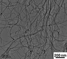
As-received CNTs ( Fig. 1) with an outer diameter of 10–20 nm and a length of several microns (∼5 μm) were mixed with pure Al (99.8% purity) or 6061Al (Al–1.2 wt% Mg–0.6 wt% Si) powders, with an average diameter of 10 μm, in a bi-axis rotary mixer at 60 r/min for 8 h with a 1:1 ball to powder ratio. The volume fractions of CNTs in the mixed powders of CNT/Al and CNT/6061Al composites were both 1.5%. The as-mixed powders were cold-compacted in a cylinder die, degassed and then vacuum hot-pressed into cylindrical billets, with a diameter of 55 mm and a height of 50 mm, at 853 K for 1 h.
 | Fig. 1. Morphology of as-received CNTs. |
The as-pressed billets were then hot forged at 723 K into disc plates with a thickness of about 10 mm. Then the plates were subjected to 3-pass in-situ FSP at a tool rotation rate of 1200 rpm and a travel speed of 100 mm/min, using a tool with a concave shoulder of 20 mm in diameter, a threaded cylindrical pin of 6 mm in diameter and 4.2 mm in length. The CNT/6061Al composite was solution treated at 803 K for 1 h, water quenched and then artificially aged at 433 K for 12 h (T6 treatment). For comparison, unreinforced Al and 6061Al were also fabricated under the same conditions.
The CNT distribution in the matrix under various fabrication conditions was examined by scanning electron microscopy (SEM, Quanta 600), field emission scanning electron microscopy (Leo Supra 35) and transmission electron microscopy (TEM, Tecnai G2 20). The CNT structure was observed by high resolution TEM (HRTEM), and the element distributions were detected by using an Energy Dispersive Spectrometer (EDS).
Tensile specimens with a gauge length of 5 mm, a width of 1.5 mm and a thickness of 1 mm were machined from the FSP composites perpendicular to the FSP direction. Tensile tests were conducted at a strain rate of 1 × 10⁻³s-1 at room temperature using an Instron 5848 microtester. The electrical conductivity of the composite and the matrix samples with a gauge diameter of 4 mm and a gauge length of 50 mm were tested by Voltmeter–ammeter Method.
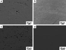
Fig. 2 shows the CNT distributions in forged and FSP composites. Large CNT clusters with sizes of several micrometers were observed under SEM for either forged CNT/Al or CNT/6061Al composite ( Fig. 2(a) and (c)). This is attributed to the fact that the low energy input of the simple mixing technique could not break the large CNT clusters. The clusters in the forged CNT/6061Al composite were much smaller than that in the forged CNT/Al composite, although they were fabricated in a similar mixing processing. This difference could be attributed to the appearance of a small amount of liquid in the CNT/6061Al composite during the stage of hot-pressing. The liquid made the interface bonding between clusters and matrix stronger, as a result the large clusters were more easily fractured into many smaller fragments during forging. After FSP, nearly no CNT clusters could be found under SEM ( Fig. 2(b) and (d)), which demonstrated that the CNTs were dispersed into the matrix. The strong mechanical effect during FSP broke down the CNT clusters and dispersed the CNTs into the matrix.
 | Fig. 2. SEM images of CNT distributions in 1.5 vol.% CNT reinforced composites: (a) forged CNT/Al, (b) FSP CNT/Al, (c) forged CNT/6061Al, and (d) FSP CNT/6061Al. (The black phases under the SEM were CNTs). |
Fig. 3 shows magnified images of CNTs in the forged and FSP CNT/6061Al composites. For the forged composite ( Fig. 3(a)), the CNT clusters consisted of a large number of CNTs, and no matrix was observed to be immersed into the clusters. This mainly resulted from the large aspect ratio of the pores in CNT clusters and the poor wetting property between CNTs and Al. Brechet et al. [30] calculated the pressure that could immerse the matrix into pores in clusters, which indicated that larger pressure should be imposed for immersing the matrix alloy into the pores with larger aspect ratio in clusters. For the FSP composite ( Fig. 3(b)), the CNTs were uniformly dispersed into the matrix. While some of the CNTs were singly dispersed, part of the CNTs was distributed in the matrix as fine CNT bundles consisting of several CNTs, which indicated that FSP could uniformly disperse the CNTs into the aluminum matrix. The severe plastic strain of FSP broke the CNT clusters on the one hand, and forced the matrix to be immersed into the pores in the small CNT clusters on the other hand. As a result, most of the CNTs were uniformly dispersed into the matrix.
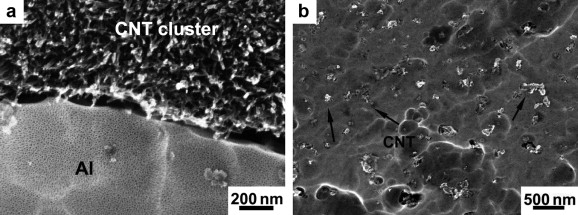 | Fig. 3. SEM images showing CNT distribution in 1.5 vol.% CNT/6061Al composites: (a) forged; (b) FSP. |
The XRD analysis demonstrated that in addition to Al peaks, weak peaks of Al4C3 were detected in the forged and FSP CNT/6061Al composites ( Fig. 4). For the forged composite, only one Al4C3 peak at 40 ° was detected. For the FSP composite, the intensity of the peak at 40 ° increased and another Al4C3 peak at 55 ° was detected. As the CNT clusters were mechanically broken down during FSP, the length of CNTs got much shorter compared with that of the as-received CNTs. A lot of defects formed at the tips of the CNTs, the carbon atoms at these places easily reacted with Al to form more Al4C3 during next FSP pass and subsequent solution treatment.
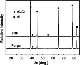 | Fig. 4. XRD pattern of T6-treated CNT/6061Al composite. |
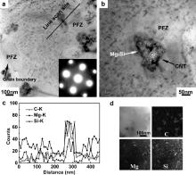
Fig. 5(a) shows the precipitation phase distribution in T6-treated FSP CNT/6061Al composite. For the CNT/6061Al composite, in most of matrix region, precipitates (β″) with a needle shape were uniformly dispersed. However, two types of zones without precipitates were found. The first type was at the grain boundaries. Generally speaking, precipitate free zones (PFZ) exist around the grain boundaries of aged aluminum alloy, such as the Al–Mg–Si and Al–Zn–Mg alloy [31]. In these aluminum alloy systems, a critical vacancy concentration is necessary to nucleate the Guinier–Preston zone (GP zone) and metastable phase. At the stage of quenching, supersaturated vacancies near the grain boundaries are easy to diffuse into the boundaries and be dissipated. Thus, the formation of the GP zone and other metastable phases in these zones is inhibited. The other type of PFZ was found at the peripheral region of CNTs, with a width of about 50 nm.
 | Fig. 5. TEM images showing precipitates in T6-treated FSP CNT/6061Al composite (a) and (b), and line scans of composition of the PFZ near CNTs (c), EDS element mapping of C, Mg and Si (d). SAED in (a) reveals fine needle phase β″. |
In Fig. 5(b), a large particle of ∼30 nm in width and ∼80 nm in length was found to attach to a CNT. The linear scans of the composition shown in Fig. 5(c) indicated that Mg and Si atoms segregated at the CNT boundaries and a zone which was poor in Mg and Si was formed at the peripheral zone of CNTs. The coarse particle attached to the CNT in Fig. 5(b) was rich in Mg and Si, and was considered to be large Mg2Si particle. The CNTs have extremely large specific surface area, and it is believed that the Mg and Si atoms were easy to segregate at the CNT boundaries during heat treatment, because the CNT–Al interfaces have many dislocations and other structure defects. This could be further proved by EDS mapping shown in Fig. 5(d). Mg and Si element segregations, which correspond to Mg2Si shown in Fig. 5(b), were observed at the CNT boundaries. As a result, the PFZ around the CNTs was formed due to the formation of the large Mg2Si particle attached to the CNTs which results in the leanness of Mg and Si at the peripheral region of CNTs.
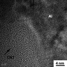
Fig. 6 shows HRTEM image of the CNT in the FSP CNT/6061Al composite. The tube structure of the CNT was still retained after FSP, which indicated that FSP did not destroy the structure integrity of CNTs. The CNTs had much larger length in the axis direction compared with that in the diameter direction. The fracture of the CNTs mainly occurred in the CNT axis direction. Thus, the tube structure could still remain well after FSP. No pores were found at the CNT–Al interfaces, which demonstrated the good bonding between CNT and Al. CNT structure integrity and good CNT–Al bonding have a great effect on the load transfer from the matrix to the CNT, which were beneficial to the strength increase for the composites.
 | Fig. 6. CNT tube structure in T6-treated FSP CNT/6061Al composite. |
The tensile properties and electrical conductivity of the composites and the alloys are shown in Table 1. For either CNT/Al or CNT/6061Al composites, the strength and ductility were increased after FSP, which mainly resulted from the uniformly dispersed CNTs. However, the elongations of the FSP composites were similar to those of the forged composites. The change of elongation could be affected by CNT distribution. CNT clustering would induce micro-void formation and therefore resulted in reduced ductility. On the other hand, the dispersed CNTs could restrain movement of dislocations during tensile deformation, reducing the ductility of the composites. For the FSP composite, although CNT clustering was fundamentally eliminated, the dispersed CNTs tended to reduce the ductility of the composites. As a result, no pronounced change in elongation was observed after FSP.
| Table 1. Tensile and electrical properties of CNT reinforced aluminum matrix composites |
For either Al matrix or 6061Al matrix, strengths of the FSP composites were increased a lot compared with those of the matrix alloy. For the FSP CNT/Al composite, the yield strength (YS) and the ultimate tensile strength (UTS) increased by about 41% and 25%, respectively, compared with those of the matrix. For the FSP CNT/6061Al composite, the YS and the UTS increased by about 33% and 17%, respectively. According to the strengthening mechanism of load transfer [32], the strength increase mainly depends on the modulus, volume fraction and aspect ratio of the reinforcement. CNTs have large modulus and large aspect ratio, producing high load transfer efficiency during tension. As a result, a large increase in strength was achieved by adding only 1.5 vol.% CNTs.
Fig. 7 shows the fractograph of FSP CNT/6061Al composite. Uniform and fine dimples were observed, which was in accordance with the relatively high elongation of 15%. Further, the CNTs were observed to be uniformly distributed on the fracture surface, which also verified the uniform dispersion of CNTs in the 6061Al matrix.
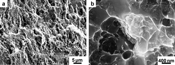 | Fig. 7. Fractograph of T6-treated FSP CNT/6061Al composite. |
The CNTs have excellent electrical properties along the CNT axis direction, evinced by the current carrying density of ~4 × 10⁹A cm-2 [33]; however the interface between CNTs and Al has a great electron scattering effect and the electrical conductivity along the CNT diameter direction is much worse. The electrical conductivity change of the composites compared with that of the matrix alloy could be attributed to the following reasons: the electron scattering at the CNT–Al interface, the electron transporting through CNT, and the microstructure change of the matrix due to CNT incorporation.
For the FSP CNT/Al composite, the electrical conductivity decreased a little compared with that of the Al matrix ( Table 1). The main influential factors are the randomly dispersed CNTs and the electron scattering at the CNT–Al interface. Because the CNTs were randomly arranged in the matrix, the electrons could not be effectively transported through the CNT axis direction. The electron scattering at the CNT–Al interfaces made this situation even more serious. As a result, the electrical conductivity of the CNT/Al composite reduced a little due to the CNT incorporation. Another phenomenon observed for the CNT/Al composite as shown in Table 1 is that the electrical conductivity of the FSP composite was similar to that of the forged composite. This indicates that the electron scattering effect at the CNT–Al interfaces is more dominant in affecting the electrical conductivity than the CNT clustering.
Table 2 compares the electrical properties of various pure metals and their corresponding composites reinforced with different contents of CNTs from references. For the pure metals without alloying, the CNTs with random orientation normally led to a decrease in electrical conductivity of CNT/metal composites. The decrease in electrical conductivity for the present FSP CNT/Al composite was much smaller than that for other composites from references ( Table 2). This is attributed to significantly reduced contaminations and improved CNT distribution during FSP.
| Table 2. Electrical properties of various pure metal matrixes and corresponding composites from references |
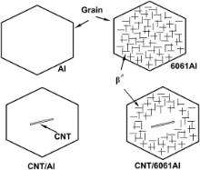
For the CNT/6061Al composite, the situation was different. The electrical conductivity of the CNT/6061Al composite increased slightly from 27.3 to 28.9 MS/m by CNT incorporation. This is considered to be mainly related with the microstructural change as shown schematically in Fig. 8. As shown in Fig. 5, the segregation of Mg and Si at the CNT boundaries resulted in the formation of PFZ which were poor in Mg and Si atoms. This means that the number of precipitates in the CNT/6061Al composites was much less than that in the 6061Al alloy. In this case, the electron scattering effect due to precipitates was weakened. This means that the electrical conductivity of the 6061Al matrix in the composite was higher than that of the 6061Al alloy without CNTs. As a result, the electrical conductivity of the CNT/6061Al composite was even increased compared with that of the 6061Al alloy.
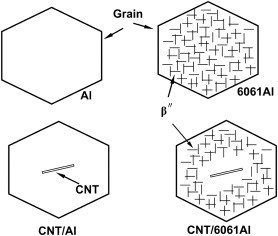 | Fig. 8. Schematic showing the electrical conductivity changes due to different microstructures. |
CNT/Al and CNT/6061Al composites with randomly oriented CNTs were fabricated by PM combined with FSP. The CNTs were uniformly dispersed in the matrix in the two composites. The tensile properties for both composites were greatly increased compared with the matrixes, due to the CNT incorporation. The electrical conductivity of the CNT/Al composite was decreased after CNT incorporation, while the electrical conductivity of the CNT/6061Al composite was increased compared with that of 6061Al alloy. The reason could be attributed to Mg and Si segregation at the CNT–Al interface after heat treatment, which resulted in the formation of PFZ at the peripheral region of CNTs as well as the decrease of Mg and Si concentrations in the matrix, and therefore the electron scattering effect was weakened.
The authors gratefully acknowledge the support of the National Basic Research Program, China (Grant Nos. 2011CB932603 and 2012CB619600), and the National Natural Science Foundation, China (Grant No. 51331008).
| 1. |
|
| 2. |
|
| 3. |
|
| 4. |
|
| 5. |
|
| 6. |
|
| 7. |
|
| 8. |
|
| 9. |
|
| 10. |
|
| 11. |
|
| 12. |
|
| 13. |
|
| 14. |
|
| 15. |
|
| 16. |
|
| 17. |
|
| 18. |
|
| 19. |
|
| 20. |
|
| 21. |
|
| 22. |
|
| 23. |
|
| 24. |
|
| 25. |
|
| 26. |
|
| 27. |
|
| 28. |
|
| 29. |
|
| 30. |
|
| 31. |
|
| 32. |
|
| 33. |
|
| 34. |
|