Search for articles:
Wenyin Xue , Weina Zhang
Corresponding authors:
Received: 2018-12-6
Revised: 2018-12-29
Accepted: 2019-03-1
Online: 2019-09-20
Copyright: 2019 Editorial board of Journal of Materials Science & Technology Copyright reserved, Editorial board of Journal of Materials Science & Technology
More
Abstract
Micromechanical behavior of a fine-grained China Low Activation Martensitic (CLAM) steel under nanoindentation was studied in this work. The grain size of the as-prepared 0.1Ti-CLAM steel is $\widetilde{5}$ μm and the average diameter of the spherical precipitates is $\widetilde{5}$ nm. Both elastic modulus and hardness decrease with increasing contact depth of the nanoindenter, following an exponential decreasing function. The abnormally large contact depths should be resulted from defect concentration under the indenter. The effect of nanosized precipitates on hardness is responsible for the pop-ins occurring in the load-depth curves, corresponding to the blockage of nanosized precipitates to the dislocation movement. Nanosized VC and M23C6precipitates with the volume fractions of 0.32% and 1.21% can be identified, respectively. Different strengthening mechanisms originated from the two types of nanosized precipitates. The blockage of dislocations by VC particles leads to an Orowan strengthening whilst dislocations could cut through theM23C6particles because of the large size of the particles. The strengthening effects originated from the VC and M23C6 precipitates lead to the strength increase of $\widetilde{4}$48 MPa and $\widetilde{2}$54 MPa, respectively.
Keywords:
Reduced activation ferritic-martensitic (RAFM) steels are the most important structural materials applied for fusion power system owing to their inherently superior thermal conductivity, thermal expansion and resistance to radiation-induced swelling and helium embrittlement compared to austenitic stainless steels [[1], [2], [3]]. Typical RAFM steels have been studied and developed in many countries, named as F82H steel in Japan, EUROFER 97 steel in Europe, 9Cr2WVTa steel in USA and China-Low-Activation-Martensitic (CLAM) steel in China [4], respectively. The stability of MX-type (M =V, Ta, Ti, Nb; X=C, N) precipitates affects mechanical properties of both RAFM and conventional ferritic-martensitic (FM) steels at the temperatures above 500 °C. When aged at 600 °C the nanosized precipitates grow up, leading to a reduced density. When the temperature reaches 700 °C, the precipitates are dissolved and re-precipitated. The precipitates showing the optimum and the inferior resistance to the aging-induced instability are TaC and TaN, respectively [5].
Up to now, 9-12Cr martensitic heat-resistant steels cannot be employed at 650 °C in engineering applications [[6], [7], [8]]. The tempered martensitic microstructure is thermodynamically metastable due to the high density of dislocations in the 9-12Cr steels [[7], [8], [9]]. Under the long-term high-temperature service, the matrix will gradually evolve into more stable recrystallized ferrite because of the thermally activated dislocation motion [8]. In the 9-12Cr heat-resistant steels, precipitates are tailored to different length scales. The larger scale applies to the M23C6 (M = Cr, Fe) carbides, with a size of 100 200 nm, and the smaller scale applies to the MX precipitates, with a size below 50 nm [[6], [7], [8]]. The first type precipitates is mainly distributed along the lath boundaries and the prior grain boundaries, preventing the migration of the boundaries and suppressing recrystallization [10]. The second type precipitates are dispersed within the matrix, hindering the dislocation motion [8]. The contribution of large M23C6 carbides to stabilizing grain boundaries has been verified by Kostka et al. [10]. In general, a closely spaced dispersion of precipitates with large dimensions (≥ 50 nm) is effective in prohibiting the migration of grain boundaries or lath boundaries. In the view of retarding microstructure evolution, the larger precipitates are desired. Liu et al. [11] have reviewed the kinetic analysis of the martensite formation and microstructural control of the high-Cr martensitic/ferritic steels. They suggested that to improve the mechanical properties (strength and ductility) of martensitic/ferritic steels at elevated temperatures for the power plant use, the refinement of original austenitic grains and the thickness of the final martensitic laths as well as the pinning effect of stable carbides should be investigated thoroughly. Very recently, the influence of Ta content on precipitation behaviors and high-temperature mechanical properties of the low-carbon RAFM steels were investigated, showing that the MX precipitates play an important role in improving high-temperature mechanical performances of RAFM steels [4].
Most studies focused on the mechanical properties of coarse-grained low C RAFM steels and the effect of alloying elements such as C [3], Ta [4,5], and V [5,12] on the deformation behaviors. However, the effect of Ti content on the mechanical properties of low-carbon RAFM steels, especially the fine-grained one, has been rarely reported. In addition, Nanoindentation can be used to measure penetration depth in the range between nanometers to micrometers. The indentation produces local plastic deformation (increase in hardness) whose expansion is constrained by the adjacent deeper material, giving rise to a field of surface compressive stress. This approach thus enables the characterization of micromechanical properties for materials [13]. Great progress has been made in determining mechanical parameters including Young’s modulus and hardness from the depth-sensitive indentation test. It has been suggested that the ratio of hardness (H) to elastic modulus (E), i.e., elastic strain to failure and fracture toughness, is an appropriate factor for determining the tribological properties of metallic and ceramic nanocomposites [14].
The objective of the current study is twofold: (i) to refine the martensitic matrix to ultrafine-grained regime through an innovative process; (ii) to quantify the effect of nanoscale particles on the mechanical properties of a low carbon CLAM steel containing 0.1 wt.% Ti. To accomplish the objectives and elucidate the relationship between structure and mechanical properties, nanoindentation tests together with post-mortem transmission electron microscopy (TEM) were performed.
The alloy was melted in a vacuum induction furnace, and an ingot of 65 mm × 65 mm × 80 mm in dimension was cast. The chemical composition of the alloy, measured by inductively coupled plasma mass spectroscopy was 8.90Cr, 0.56 Mn, 0.15 Ta, 0.10 Ti, 0.15 V, 1.40 W, 0.06 Si, 0.09 C, 0.004 P, 0.004 N (in wt.%), and balance Fe. The ingot was homogenized in an air furnace at 1200 °C for 2 h to remove the inhomogeneous microstructure evolved during solidification, and then hot rolled at starting temperature of 1150 °C to ensure complete dissolution of carbide particles formed during homogenization via 7 passes to a thickness of 15 mm (ε = 81%) and final temperature of 800 °C. Subsequently, the plate was annealed at 980 °C for 0.5 h and water quenched to room temperature to obtain a fully martensitic microstructure. Finally, the plate was tempered at 760 °C for 1.5 h and cooled to room temperature in air.
The grain morphology of the as-processed steels was characterized using scanning electron microscopy (SEM, JXA-8530 F, Japan). The RD-TD planes of the specimens were mechanically polished and then electropolished to remove the surface damage induced by grinding and mechanical polishing. The electrolyte consisted of 4 vol.% nitric acid and 96 vol.% ethanol.
For TEM observation, slices of 60 nm were cut from the steel at the vicinity of the nanoindentation, using a focused ion beam (FIB, Tescan Lyra3 XM). TEM studies were performed in a Tecnai G2 20 microscope, operated at an accelerated voltage of 200 kV.
Uniaxial tension along the rolling direction (RD) of the as-fabricated steel was performed at room temperature with a strain rate of 6 × 10⁻³ s-1 under RT. The dog-bone shaped specimens with a gage length of 15 mm and a width of 4 mm, and the final thickness of 1.2 mm were cut from the middle of the as-prepared steel by using wire electrical discharge machining. Uniaxial tensile tests were performed on a SANS micro-force testing system. A contactless MTS LX300 laser extensometer was used to calibrate and measure the sample strain upon loading.
Hardness-depth profiles were obtained from the instrumented indentation measurements on the polished cross-sections using a Triboindenter (Hysitron Incorporated, USA) equipped with diamond Berkovich tips. The tips are with pyramidal shape and the radius of the tip is approximately 75 nm. The specimens were cut from the as-prepared steel using an electron discharge machine, mechanically polished with standard metallographic procedures, and finally polished with diamond polishing paste. The specimens were first loaded to the maximum load of 2000 μN at a constant loading rate of 50 μN/s and held for 5 s. The same procedure was performed repeatedly to reach different depths in the RD-ND (rolling direction-normal direction) planes of the as-prepared samples. Then, the specimens were unloaded until the load was removed completely in 5 s. For each specimen, 16 indents were obtained to form a 4 × 4 lattice matrix with a spacing of 5 μm, and then the average hardness value was extracted from the indentation data. The results obtained from load controlled indentation were analyzed according to Oliver and Pharr [15]. Nanoindentation hardness is defined as the indentation load divided by the projected contact area. Elastic modulus can be obtained from initial unloading contact stiffness [16]:
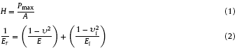
where H is hardness, Pmax is the maximum of the applied force, A is the projected contact area depending on the contact depth, υ is Poisson’s ratio, and Er is the reduced Young’s modulus that can be determined by the measured elastic contact stiffness, S, as follows:

The above relation is independent of the indenter geometry. Therefore, the elastic modulus and the contact area can be deduced from the initial unloading slope of the load-displacement curves [16].
Fig. 1(a) shows that the grain size of the as-prepared 0.1Ti-CLAM steel is 5 μm, which is obviously smaller than the reported conventional CLAM steel ($\widetilde{2}$0 μm) [17]. SEM observation indicates numerous fine precipitates located along grain boundaries (Fig. 1(b)). To determine the size of the precipitates, TEM observations were conducted, showing numerous nanosized precipitates in the martensitic matrix (as indicated by yellow arrows in Fig. 1(c)). Meanwhile, a few dislocation heads with stress field were indicated by the circles. Statistical histogram indicated that the average diameter of the spherical precipitates is 5 nm (Fig. 1(d)).
Fig. 1. (a) Metallographic morphology of the as-prepared 0.1Ti-CLAM steel showing that the average grain size is 5 μm. (b) SEM observation indicating numerous precipitates located along the grain boundaries, (c) TEM image showing the nanoscale precipitates embedded in the matrix, and (d) statistical histogram indicating average diameter of the spherical precipitates is 5 nm.
The significant refinement of grain size can be attributed to the Ti addition. Han et al. reported that the finer TiC was more effective to refine grain size [18]. They suggested that grain growth is retard as the grain boundary intersects the TiC located in the grain boundaries, leading to the decreasing driving force for grain boundary movement [18].
Fig. 2 shows typical engineering tensile stress-strain curve for the as-prepared 0.1Ti-CLAM steel, in comparison with that for the coarse-grained (CG) CLAM steel (grain size $\widetilde{2}$0 μm) [17]. Obviously, as-prepared sample exhibits significantly higher strengths than that of its CG counterpart. For the as-prepared 0.1Ti-CLAM steel, the tensile yield strength σy (at 0.2% offset) reaches as high as 590 MPa and the tensile strength σTS is 670 MPa, which are remarkably higher than those of the CG CLAM steel (σy is 540 MPa and σTS is 615 MPa) [17]. It is interesting to note that the elongation increases considerably with Ti addition. For the as-prepared 0.1Ti-CLAM steel, the elongation can be as high as 27%. This impressive tensile ductility is obviously higher than the value of 24% for the CG CLAM steel [17]. A slight strain hardening appears in the major plastic deformation stage for each sample, indicating some dislocation accumulation during the plastic straining prior to failure.
Fig. 2. Engineering stress-strain curves for the as-prepared 0.1Ti-CLAM steel, compared to the coarse-grained CLAM steel [
The increasing strengths and ductility in the as-prepared 0.1Ti-CLAM steel must be associated with grain refinement, which was derived from the Ti addition along with multiple rolling processes. Though ultrafine grained steels show excellent tensile properties such as high initial strain hardening rate and high tensile strength [19,20], their elongation is small when compared to the coarse-grained counterpart [18]. Hence, the uniform dispersion of nanoscale precipitates has been employed to improve strength and ductility simultaneously. Some researches of precipitation effects on microstructure and mechanical properties in Ti-bearing steels have illustrated that the precipitates can lower the grain growth rate by pinning the grain boundaries, resulting in the increasing strength and toughness of steels [18,21,22].
To explore the mechanical properties of the 0.1Ti-CLAM steel, the specimens were loaded to the maximum load of 2000 μN at a constant loading rate of 50 μN/s and held for 5 s. Fig. 3(a) shows the morphologies and positions of the 15 nanoindentations in the 0.1Ti-CALM steel under SEM observation, as indicated by yellow arrows. Close observation reveal the magnified image of nanoindentations 4#, 5# and 9#, and arrows and break-lines indicate the nanoindentations and grain boundaries, respectively (Fig. 3(b)). Clearly, the morphology of the nanoindentations changes significantly with the varied position. For example, 3# indentation is an equilateral triangle and the size is the smallest among the nanoindentations. This may be related to the numerous fine precipitates in white around it. However, the 0#, 1# and 2# indentations exhibited the larger size and the side in the fourth quadrant is larger (Fig. 2(a)), hinting that the grain under nanoindentation is anisotropic. Fig. 3(b) shows the magnified morphologies of 4#, 5# and 9# indentations, and the dot-dashed lines in red represent grain boundaries. It is interesting to note that these indentations well fall at grain boundary (4#), grain interior (5#), and the region close to grain boundary (9#), respectively. Moreover, 5# indentation owns the largest size and the shape is an isosceles triangle compared to an equilateral triangle of 4# and 9# nanoindentations. Thus, different mechanical behaviors are expected for the three nanoindentations.
Fig. 3. (a) SEM observation of the morphology and position of 0# 15# nanoindents in the 0.1Ti-CALM steel, and (b) the magnified image of the nanoindents 4#, 5# and 9#. Arrow and break-line indicate the nanoindents and grain boundaries, respectively.
Typical load-depth curves corresponding to the studied 16 indentations in Fig. 3(a) are shown in Fig. 3. It is obvious that the displacement of indenter at each position is different, although it is indented with identical force and strain rate. As far as the 2# indentation is concerned, the contact depth (hc) is the largest, i.e., 293 nm (curve 2, Fig. 4(a)). The 13# indentation shows the smallest hc of 100 nm (curve 13, Fig. 4(b)). According to Eqs. (1), (2), (3), Er and H are determined to be 70 ± 1 GPa and 0.74 ± 0.05 GPa for 2# indentation whist that are 182 ± 1 GPa and 4.91 ± 0.05 GPa for 13# indentation, respectively. The values of hc, Er and H derived from the typical load-depth curves of the 16 indentations are listed in Table 1. It is interestingly to note that Er and H varied significantly for different indentation positions. To explore the fundamental mechanism concerning with the variation of Er and H, the magnified load-depth curves of the different indentations are shown in Fig. 4(c) and (d). Obviously different features can be found from these curves. First, numerous stages occur in all the 16 curves. Second, the hc values of 2#, 6#, 11# and 14# indentations are significantly higher than that of other indentations under the identical loading force. For example, at a loading of 100 μN, hc is 10 μm for 4# indentation whilst it remarkably increases to 78 μm, 54 μm, 50 μm and 32 μm for the 2#, 6#, 14# and 11# indentations, respectively (Fig. 4(c) and (d)).
Fig. 4. Loading-displacement curves of nanoindentations for the 0.1Ti-CLAM steel. (a) 0#-7# indenters, (b) 8#-15# indenters, (c) magnification of one segment of the curves in (a), and (d) magnification of one segment of the curves in (b).
Table 1 Relationship among indentation position, contact depth (hc), elastic modulus (Er) and hardness (H) in the 0.1Ti-CLAM steel.
| No. | hc ± 0.02 nm | Er ± 1 GPa | H ± 0.05 GPa |
|---|---|---|---|
| 0 | 135 | 148 | 3.28 |
| 1 | 132 | 161 | 3.36 |
| 2 | 293 | 70 | 0.74 |
| 3 | 160 | 131 | 2.36 |
| 4 | 132 | 154 | 3.38 |
| 5 | 136 | 146 | 3.19 |
| 6 | 260 | 77 | 0.93 |
| 7 | 168 | 124 | 2.16 |
| 8 | 131 | 157 | 3.44 |
| 9 | 154 | 135 | 2.54 |
| 10 | 135 | 153 | 3.24 |
| 11 | 167 | 123 | 2.15 |
| 12 | 154 | 127 | 2.57 |
| 13 | 100 | 182 | 4.91 |
| 14 | 211 | 98 | 1.40 |
| 15 | 145 | 138 | 2.83 |
Fig. 5 shows the variation of Er and H with hc under a load of 2000 μN at a constant loading rate of 50 μN/s. Evidently, both Er and H decrease with increasing hc. By fitting the experimental data with an exponential decreasing function, the following equations correlating Er and H to hc can be obtained:
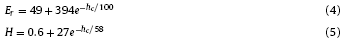
Fig. 5. Variation of hardness and elastic modulus with increasing contact depth (hc) in the 0.1Ti-CLAM steel.
respectively. Based on the von Mises flow rule, Nix and Gao [23] used Tabor’s factor of 3 to convert the equivalent flow stress to hardness, H:

where H0 is the hardness that arises from the statistically stored dislocations alone, and hc* is a length that characterizes the depth dependence of the hardness. According to Eq. (6), it is reasonable that hardness decreases with increasing contact depth. Nevertheless, our results suggest that other factors should also play a role during nanoindentation on the 0.1Ti-CALM steel. The large contact depths of 2#, 6#, 11# and 14# indentations should be resulted from the defects such as voids and holes under the indenter. In addition, this may also be related to the experimental error or microstructure inhomogeneity. It is well established that Er is a characteristic quantity for metallic materials. However, the measured Er values for the above-mentioned indentations are 70, 77, 123, and 98 GPa (Table 1), respectively. They are significantly lower than the value of 140-210 GPa for the conventional steels.
Spaepen [24] suggested a plastic flow model to construct the relationship between flow concentration (cf) and strain (ε) in metallic materials:

where kf=νexp(-ΔGmkT, Δf is the fraction of potential jump dots, v is atomic vibration frequency, Ω is atomic volume, ΔGm is activation energy, k is Boltzman constant, T is temperature, σ is flow stress, v0 and ε0 are volume fraction and strain of mobile defects, respectively. In nanoindentation, Eq. (7) can be rewritten as:

Thus, loading rate increases with increasing defects concentration, i.e., the larger contact depth resulting from the more significant defect concentration under an identical loading force (dhc/dt ∝ cf). It is reasonable to note that the corresponding hardness is 0.74, 0.93, 2.15 and 1.40 GPa for 2#, 6#, 11# and 14# indentations (Table 1), respectively. In contrast, the highest hardness of 4.91 ± 0.05 GPa is obtained for 13# indentation because grain boundaries and the numerous fine precipitates were observed near the indentation (Fig. 3(a)).
The effect of nanosized precipitates on hardness should be associated with the stages occurring in the load-depth curves (Fig. 4(c)) and (d)). These stages are also noted as pop-ins, which were related to the emission of individual shear bands underneath the indenter tip within amorphous materials [25,26]. For amorphous materials, the presence of shear bands is readily identified as a series of steps around the periphery of the indentation. Here, each pop-in event corresponds to the blockage of nanosized precipitate to the dislocation motion, resulting in a peculiar hardening behavior. As the loading force increases, dislocation can overcome the pinning force of one nanosized precipitate and slip further, leading to the first yield (Fig. 3(c) and (d)). Subsequently, the hardening gradually diminishes, leading to another pop-in and yielding as the dislocation interacted with the next nanosized precipitate.
TEM observations were employed to reveal the role of nanosized precipitates during nanoindentations for the 0.1Ti-CLAM steel. Fig. 6(a) shows dense dislocations emitted from the tip of an indenter (indicated by arrow), and a square-like precipitate at the path of dislocations slip (indicated by triangle in Fig. 6(b)) was identified as MX by using an energy-dispersive X-ray analysis (EDX) (Fig. 6(c)). The representative EDX spectra indicate that these MX carbides have a chemical composition of 39.34C, 29.36Ta, 28.55Ti, 0.18Cr, and 2.53Fe in at.%. In addition, numerous dislocations are observed in the martensite (Fig. 6(d)). Close observation in Fig. 6(e) shows that the dislocations are tangled with nanosized precipitates. Subsequently, high-resolution TEM observations are performed to discern the fine precipitates. The obtained lattice image clearly indicates that the spherical precipitate is VC with a diameter of 5 nm. The crystallographic relationship of the precipitate with the matrix is incoherent fulfilling the {-1-11}VC//{-10-1}matrix relationship (Fig. 6(f)). The corresponding diffractogram were obtained by using fast Fourier Transformation (FFT) for VC phase (Fig. 6(g)) and α-Fe matrix (Fig. 6(h)). The VC phase were incoherent with α-Fe matrix along the [01-1]VC direction, with an interplanar spacing of 0.243 nm for the (1-11)VC plane of VC phase, namely the Kurdjumov-Sachs (K-S) misorientation relationship is fulfilled [30]. These phenomena give a well explanation for the observed abnormal work-hardening, i.e., pop-ins in Fig. 4 for the studied steel.
Fig. 6. TEM image showing (a) dense dislocation emitted from the tip of indenter in the deformed 0.1Ti-CLAM steel (indicated by arrow), (b) a square-like precipitate at the path of dislocations slip (indicated by triangle). (c) EDS analysis showing that the precipitate is MX, (d) TEM image showing numerous dislocations in martensite and (e) close observation of the dislocations tangled with nanosized precipitates. (f) The high resolution TEM image revealing that the fine precipitate with a diameter of 6 nm (circled in (e)) is incoherent with the matrix. The corresponding diffractogram obtained by fast Fourier Transform (FFT) patterns for the matrix (g) and nanoparticle (h).
Concurrently, the square-like and spherical precipitates were observed in a grain and at its boundary, which were labelled 1 and 2, respectively (Fig. 7(a)). They were identified as M23C6 by using EDX (Fig. 7(b) and (c)). The representative EDX spectra indicate that these M23C6 carbides have a chemical composition of 16.41C, 34.55Cr, 1.79 W, and 47.23Fe for the square-like precipitate (Fig. 7(b)) whilst those for the spherical one are as follows: 27.76C, 33.68Cr, 0.17 V, 2.29 W, and 36.06Fe in at.% (Fig. 7(c)). Indeed, precipitation of M23C6 carbide, where M means metallic elements such as Cr, V, W, etc., has been a long-standing hot topic for ferritic and austenitic stainless steels containing Cr and C [[27], [28], [29]]. M23C6 is a Cr-rich carbide which possesses a complex cubic structure. It includes 92 atoms per unit cell, with a lattice parameter of about 1.06 nm which is approximately four times larger than the iron matrix. Indeed, it has been well established that M23C6 carbides are extremely beneficial to work-hardening through prohibiting dislocation motion by dislocation tangling and pinning [[27], [28], [29]]. It should be pointed out that the EDX analysis provides qualitatively chemical composition with a wide error range of 2%-20% associated with the surface status of specimen as well as the selected correction factor. Hence, we mainly use the EDX data to determine the element type in the precipitates.
Fig. 7. (a) TEM image showing a square-like and a spherical nanoparticle in the grain and at the boundary. The corresponding EDS results supporting that the precipitates are M23C6, as showing in (b) - (c).
It is well accepted that VC is a highly stable phase because its stability in terms of phase transformation and grain coarsening has been well demonstrated. Finely dispersed precipitates tangled with dislocations can be found everywhere (Fig. 6(f)). Dislocation lines, pinned by two or more precipitates and bowing out to surmount plastic deformation are indicated by the arrows in Fig. 6(a) and (b). This suggests that the finely dispersed precipitates are beneficial for the increase in dislocation density during plastic deformation by restraining the recovery and annihilation of dislocations. It is conceivable that as the deformation proceeds, more dislocations are blocked and tangled around the nanosized precipitates. Consequently, the stress increases rapidly to a high level that induced localized plastic flow. The dislocations in a material can interact with the precipitates in one of two ways. If the precipitate particles are soft, dislocations would cut through the particles. For hard precipitate particles, however, looping and bowing of dislocations would occur and result in the multiplication of dislocations (Fig. 8). Hence, dislocations will preferably cut across an obstacle if the matrix and the precipitate are coherent precipitates, otherwise dislocations will bypass when the matrix and the precipitate are incoherent [31]. As the dislocations moved to a region near the VC particles, they showed a tendency to bypass the VC phase (Fig. 8), leading to an Orowan strengthening [32]. A similar scenario has been reported by Sasaki et al. [33]. Based on the well-known Orowan mechanism, the following relationship is used to estimate yield strength contribution from the precipitation alone [32,33]:
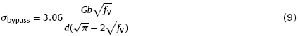
Fig. 8. (a) TEM observation of the MX-type precipitates that pinning dislocations in the 0.1Ti-CALM steel. The short-dotted lines indicate dislocations and the arrows indicate MX precipitates, respectively. (b) A schematic illustration of the Orowan strengthening mechanism.
where fv is the volume fraction of the precipitates, b is Burgers vector (2.85 × 10⁻¹⁰ m), d is the precipitate diameter, and G is the shear modulus ($\widetilde{7}$6 GPa). Obviously, a decrease in the precipitate size and an increase in the precipitate volume fraction lead to the increase in the strength of the material. The volume fraction of the VC precipitates has been estimated to be fv = 0.32 % using TEM observation and JMatpro calculation (Fig. 9), because of the precipitates serving as a phase totally different from that of the matrix. Consequently, the increase in yield strength from the precipitates is determined as 448 MPa by using Eq. (9). Obviously, the large hardness in current sample originates from the strengthening effect of the high density of nanoparticles.
Fig. 9. Phase diagram of the 0.1Ti-CLAM steel calculated by JMatPro.
On the other hand, dislocation could cut through the M23C6 particles because of the large size. Hence, the following equation can be used to estimate the yield strength according to the Cut - through mechanism:
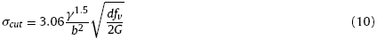
where γ is interfacial energy ($\widetilde{1}$5 mJ/m2), fv is the volume fraction of the precipitates, b is Burgers vector (2.85 × 10⁻¹⁰ m), d is the precipitate diameter (30 nm), and G is the shear modulus ($\widetilde{7}$6 GPa). The volume fraction of the M23C6 precipitates has been estimated to be fv = 1.2 % by TEM observation and JMatpro calculation (Fig. 9). Consequently, the increase in yield strength from the precipitates is determined as 254 MPa using Eq. (10).
As the hard particles in the matrix prohibit dislocations to cut through and bow out, the total dislocation density, ρ, can be estimated using the equation [34]:

where ρs is the deformation-driven dislocation density of matrix, Δρ is the increment of dislocation density associated with hard particles, and ε˙ is the shear strain rate. The above deduction can be confirmed by the TEM observations in the deformed steels, as shown in Fig. 8. The edges of VC particles appear to be extremely blurred because of the pile-up of dislocations. In the deformed 0.1Ti-CLAM steel, dislocations are blocked at the boundaries of the particles, as indicated by arrows.
Hence, our study demonstrates that the combination of warm rolling, intermittent annealing as well as the addition of titanium is a novel approach to obtain fine grains, nanosized precipitates and high strength for CLAM steels. The grain size of steel has been significantly refined to be $\widetilde{5}$ μm, which is consistent with the recent findings that the nanosized particles play an important role in the refinement of the matrix [35,36]. Furthermore, the current study suggests that the nanosized precipitates promote plastic deformation of fine-grained steels by enabling dislocation slip close to the particles. It is our hypothesis that to obtain the desired ductility without sacrificing the strength, an optimum combination of size and volume fraction of matrix grains and precipitates can be achieved by tuning the fabricating route for the studied CLAM steel.
Fine-grained 0.1Ti-CLAM steel with nominal a chemical composition of Fe-8.90Cr-1.40W-0.56Mn - 0.15Ta-0.10Ti-0.15V-0.09C-0.06Si-0.004P-0.004 N (wt.%) was prepared by performing hot-rolling, water quenching and tempering subsequently. Mechanical properties of the steel were investigated under nanoindentation test and the main results can be summarized as follows:
(1)The grain size of the as-prepared 0.1Ti-CLAM steel is 5 μm whilst numerous fine precipitates are located along the grain boundaries. The average diameter of the spherical precipitates is 5 ± 1 nm.
(2)It is interestingly to note that Er and H change significantly with the varied indentation positions. Both Er and H decrease with increasing contact depth of the nanoindenter, following the exponential decreasing functions Er=49+394e-hc/100 and H=0.6+27e-hc/58. The abnormally large contact depths are attributed to the high defect concentrations under the indenter at identical loading force.
(3)The effect of nanosized precipitates on hardness is responsible for the featured stages occurring in the load-depth curves. Each pop-in event corresponds to the blockage of nanosized precipitate to the dislocation motion, resulting in a peculiar hardening behavior.
(4)Nanosized VC and M23C6 precipitates with the volume fraction of 0.32% and 1.21% are identified in the fine-grained 0.1Ti-CLAM steel, respectively. The dislocations indicate a tendency to bypass the VC phase, leading to an Orowan strengthening. However, dislocation cut through the M23C6 particles because of the large size. The strength increase contributed by the VC and M23C6 precipitates is evaluated to be 448 MPa and 254 MPa, respectively.
This project is supported by the National Natural Science Foundation of China (NSFC, Grant Nos. 51574079, U1460204, U1660117), and the National Key Research and Development Program of China (No. 2016YFB0300602).
The authors have declared that no competing interests exist.

 WeChat
/
| 〈 |
|
〉 |


