Search for articles:
Xuan Ge , Wenquan Lu
Corresponding authors:
Received: 2019-01-10
Revised: 2019-03-5
Accepted: 2019-03-5
Online: 2019-08-05
Copyright: 2019 Editorial board of Journal of Materials Science & Technology Copyright reserved, Editorial board of Journal of Materials Science & Technology
More
Abstract
The aerodynamic levitation provides an efficient technique for the research on thermophysical properties and solidification behavior of refractory materials. However, there is a nonnegligible temperature differences across sample, causing unexpected uncertainty of measurement, such as, thermal expansivity and undercooling limit. We establish thermal filed model with properly simplified boundary condition, and derive quantitative expressions of this ambiguous temperature difference. Here we show that the temperature difference not only related to the average temperature, relative size and thermal conductivity of sample, but significantly influenced by the rotation pattern of sample. A huge temperature differences is almost inevitable when the sample with low thermal conductivity and high melting point is smelted in stationary suspension pattern, however, a drastically reduction of temperature difference can be fulfilled by simply making the sample rotation in up to down pattern. The thermal filed simulation was used to confirm the validity of these theoretical expressions. This work shed light on temperature difference in aerodynamic levitation. Based on this work, one can simply estimate the extent of temperature difference across the sample, and regulated that conveniently if needed, which benefit for novel material preparation and solidification mechanism study based on this technique.
Keywords:
As an economic, convenient and flexible levitation technology, aerodynamic levitation (ADL) has been widely used in applications such as the fabrication of novel/metastable materials [1,2], the measurement of thermophysical properties [3,4], and the study of high temperature phase transition and oxide melt structure [[5], [6], [7], [8]]. In contrast to electromagnetic levitation (EL) achieved by the magnetization force, ADL utilizes the airflow to balance the gravity. Therefore, the ADL process has a wider range of applications than EL, such as the levitation of semiconductors and insulators [9]. Comparing with the ESL process in a vacuum environment [10,11], the volatilization of oxygen element can be largely avoided in ADL with a controllable atmosphere, which benefits for stabilizing the chemical composition ratio of high temperature oxide ceramic melts.
As shown in Fig. 1(a), ADL usually heats the sample top surface by a focused laser and levitates the sample through an air stream from the bottom [12]. The distinct heating and cooling regions result in a considerable temperature differences across the sample. For example, the temperature difference may exceed 100℃ during the ADL process of crystalline Y2O3 when it is approximately heated up to the melting temperature [13]. This inevitable temperature difference not only makes an impact on the direction of crystal growth [14] and microstructure evolution [15] but also introduces convective flows, density gradient and surface tension gradient in the suspended droplet. As a result, the thermophysical property measurement could be interfered by the inhomogeneous temperature. And even then, the researchers still remain a high enthusiasm to work on heterogeneous nucleation in metals [16] and solidification kinetics in oxide ceramics [17,18] based on ADL. Especially, the studies on solidification kinetics in undercooling solidification provide insights in fabricating materials with a unique structure and excellent properties [19,20]. In most of the above cases, the temperature difference is ambiguous or neglected. Whether the inhomogeneous temperature influence the research of solidification mechanism? Whether the temperature difference can be manipulated or even avoided? The resolution of these problems depends on an in-depth study and quantitative description of temperature differences in ADL process.
Fig. 1. (a) Schematic diagram of ADL devices; (b) an illustration of heat transfer process between the droplet and surrounding environment.
In order to effectively address the temperature difference, Langstaff et al. reported an ingenious design with an additional heating laser beam at the bottom of sample [3]. However, this design significantly increases the complexity and cost of ADL devices, and cannot be used in some specific cases [21]. In another work, Schroers et al. derived an equation to describe the temperature difference of single laser heating [22]. However, this equation does not fit the actual ADL process, because the heat convection between sample and environment has not been considered. In addition, the sample position is not absolutely stationary during ADL due to the tilt and rotation. These facts promote us to consider not only the heating and cooling condition but the motion state of the sample in the investigation of the temperature difference within the sample.
In present work, the theoretical expressions of maximum temperature difference in two typical rotation modes during conventional ADL process were derived, and the validity of analytic solution was confirmed by simulation. Furthermore, a novel functional ceramic BaTi2O5 (BT2) was taking as an example to demonstrate the influence of temperature difference on the undercooling solidification process. The manipulation of temperature difference is significant for the preparation of texture BT2 materials [23] and the measurement of the thermophysical properties of BT2 melts [24]. In here, an accurate continuous cooling transition (CCT) diagram was obtained for a small temperature difference situation, which provides insights and guidance for preparing metastable BT2 materials with a superior dielectric property [25] and BT2-based glass materials with a high refractive index [26].
In aerodynamic levitation process, oxygen (99.999%) gas provided the aerodynamic force, and the gas flow was manipulated by a mass flow controller (the full range, 100 ccm). The sample was melted and maintained at a desired temperature by a 100 W CO2 laser, and the laser exposure region was always located at the droplet top surface. A high-resolution CCD camera was used to monitor the rotation and vibration of the sample to determine the levitation status. The temperature-time profile was recorded by an infrared thermometer (wavelength, 1.255 μm). However, the infrared thermometer only measured the surface temperature of the sample top, which might result in an inaccurate temperature measurement. The rotation pattern of the sample was controlled by the shape of the air outlet of the nozzle at bottom. A regular circular air outlet was used to allow the sample to be levitated in stationary or rotated in a right to left motion. While a circular air outlet with an unsmooth beveled edge can be used to move the sample in a up to down rotation pattern.
Pure BaCO3 (99.95%) and TiO2 (99.99%, rutile) powders were stoichiometrically weighted in the composition of BaTi2O5 and mixed in an agate mortar for 2 h with adding in a small amount of ethanol to improve the mixture uniformity. The powder samples were then pressed into tablets with a diameter at 20 mm and a thickness at 2 mm. These tablets were sintered at 1000 ℃ for 12 h and finally grinded into small pieces (10 mg) for the following ADL experiment.
The sample morphology was analyzed by scanning electron microscopy (SEM, Phenom XL), and the solidified phases were investigated by Cu Kα X-ray diffraction (XRD, Rigaku Ultima IV). The heat flow curves of BT2 glass during the continuous heating process was obtained by differential scanning calorimetry (DSC, Netzsch STA449 F3).
As described in the introduction, both the external factors (laser power, gas flow velocity, the position of heating region, and the nozzle shape) and the internal factors (the thermal conductivity of sample and the movement of the droplet) affect the temperature difference within the sample. In order to quantitatively analyze the temperature distribution, mathematical expression of the temperature field must be established. ADL has a complicated thermal conduction within the sample and heat convection/radiation between the sample and environment, which introduces an unsolvable boundary condition for the temperature field equation. Therefore, some assumptions and simplifications were adopted in this study:
1) The sample was simplified to a perfect sphere in simulation, although it was slightly ellipsoidal during the practical experiment [3].
2) The shape of sample always remains spherical symmetry, and the physical properties were assumed as isotropic. Therefore, the model of the heat transfer process was simplified from a three-dimensional condition to a two-dimensional situation.
3) As the sample is small, a balanced state can be easily reached with in the droplet. Thus, the heat transfer process could be considered as a steady-state thermal conductivity situation.
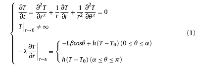
In the conventional ADL process, when the sample has a stationary position or only rotates around the laser incident direction (z axis) in a right to left movement, the heat transfer equation in polar coordinates can be described as:
If the sample rotates around x or y axis in a up to down motion, which is equivalent to a situation of the laser beam rotating around x or y axis for heating a stationary sample. Due to the extremely fast rotation in this case, the laser exposure is simplified into a uniform annular heating source. As a result, the heat transfer equation in polar coordinates can be written as:
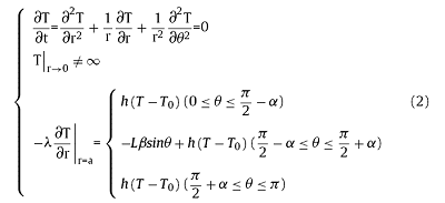
where λ is the heat conductivity, L is the laser power, β is the laser absorption ratio, a is the radius of sample, α is the central angle of heating region as shown in Fig. 1(b), sinα=d/2a, in which d is the laser beam diameter; h is the heat transfer coefficient, T0 is the ambient temperature.
The heat transfer between the sample and surrounding environment is mainly composed of the thermal convection and the heat radiation. Therefore, the heat transfer coefficient h is the sum of the convective heat transfer coefficient hc and the radiation heat transfer coefficient hr. According to Stephen Whitaker et al [27], the convective heat transfer coefficient was calculated by Eq. (3). The radiation heat transfer coefficient can be calculated by Eq. (4).
hc=$\frac{\lambda_0}{2a}(0.4Re^{\frac{1}{2}}+0.06Re^{\frac{2}{3}})Pr^{0.4}(\frac{\mu_s}{\mu_0})^{\frac{1}{4}}$(3)
hr=σε(T2+$T^2_0$)(T+T0) (4)
where λ0 is the thermal conductivity of oxygen, Re is the Reynolds number, Pr is the Planck number, μs is the dynamic viscosity of oxygen at the sample surface, μ0 is the dynamic viscosity of oxygen in ambient temperature. σ is the Stefan-Boltzmann constant, ε is the total hemispherical emissivity, and T is the temperature at sample surface.
The gas velocity around the sample surface and the surface temperature are not uniform distributed during the experiment, which results in that the heat transfer coefficients hc and hr are a function of polar angle θ. Unfortunately, the relationship between h and θ makes the temperature field Eqs. (1) and (2) difficult to be resolved analytically. In order to obtain the temperature distribution, the boundary condition is simplified in this study. In general, the radiation is not uniform within the sample, which is stronger at high temperature region than that at the low temperature region. While the convective heat transfer has an opposite trend. By considering both of heat radiation and convective heat transfer, the total heat transfer at the sample surface was roughly simplified to a uniform distribution, and the heat transfer coefficient h is approximately the sum of average convective heat transfer coefficient $h_{\bar{c}}$ and average radiation heat transfer coefficient $h_{\bar{r}}$. In a stable levitation, the airflow around sample is laminar, and the average gas velocity can be obtained based on the force balance condition [12]. The average convective heat transfer coefficient $h_{\bar{c}}$ can be calculated according to the average gas velocity. In ADL experiment, the measured region of infrared thermometer was the top surface. Thus, the measured temperature T should be higher than the average temperature used to calculate the average radiation heat transfer coefficient $h_{\bar{r}}$.
In a simplified linear boundary condition, the analytical solution of thermal field (1) and (2) can be expressed as series. Since the series solution is convergent, the first two or three terms can be used to described the maximum temperature differences to a certain extent within the sample. The solution of Eqs. (1) and (2) are written as expressions (5) and (6), respectively. Detailed derivations are documented in supporting materials.
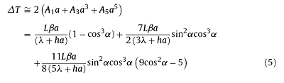
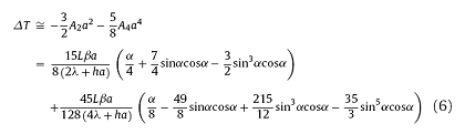
The droplet has a small radius (a ≤ 0.0015 m), which means $\frac{\lambda}{a}$≫h. Then the temperature differences expression can be simplified as:
ΔT≅$\frac{L\beta{a}}{\lambda}(1-cos^3\alpha-0.2084sin^2\alpha{cos^3}\alpha+2.475sin^2\alpha{cos}^5\alpha)$ (7)
ΔT≅$\frac{L\beta{a}}{\lambda}(0.1735\alpha+0.7794sin\alpha{cos}\alpha+0.1191sin^3\alpha{cos}\alpha-0.7251sin^5\alpha{cos}\alpha)$ (8)
From the expression (7) and (8), the temperature difference is influenced by the droplet radius, the thermal conductivity of sample and laser heating power and heating region. However, estimation of the temperature differences based on laser power is always unavailable, because the laser absorption ratio of β is unknown. Fortunately, the heat input and output keep a balance in the case of steady state heat conduction. Thus, the item of Lβ can be calculated by the total heat transfer h.
For the right to left rotation movement:
Lβ=$\frac{4h(T-T_0)}{(sin\alpha)^2}$ (9)
For the up to down rotation movement:
Lβ=$\frac{2h(T-T_0)}{\alpha+sin\alpha{cos}\alpha}$ (10)
It is difficult to measure the temperature differences within the sample in ADL process. Therefore, there are a few experimental data can be used to verify the temperature differences solution obtained in this study (expressions (7) and (8)). In a previous work, Yasutomo Arai evaluated the temperature differences in the synthesis of spherical alumina single-crystal by ADL process [14]. The droplet was remained stationary or slightly rotated around z axis, and a huge temperature difference of approximately 403 K between the top of sample and solid-liquid interface (at the bottom of sample) was observed. By this method, we calculated the maximum temperature difference across a molten alumina sphere with the same volume in a wide average temperature range from overheating (2600 K) to undercooling (2000 K), and the result was presented in Fig. 2(a). As a contrast, the maximum temperature difference under another rotation pattern (up to down rotation) was also calculated. All the calculation was conducted based on the Eqs. (3), (4), and (7), (8), (9), (10), and the physical quantities used were listed in Table 1. It should be noted that the crystalline alumina thermal conductivity (33 W m-1 K-1) was used for molten alumina, which is not accurate, because the thermal conductivity of the molten is often lower than that of crystal. However, the convection within the molten will increase the heat transfer significantly, and this effect cannot be quantified. Therefore, the known crystalline thermal conductivity is an alternative choice.
Fig. 2. Calculated temperature differences within the sample with two different types of rotation motion. (a) Relationship between temperature differences and average temperature when sample with a radius at 1 mm. (b) Influence of relative laser exposure area on the temperature differences with a constant average temperature at 2373 K. The insert graph is an enlargement of (b) in the range of temperature differences ΔT from 0 to 900 K.
Table 1 Physical quantities used in the temperature differences calculation of alumina melt at temperature close to its melting point.
| Property | Sample [unit] | Value |
|---|---|---|
| Atmosphere temperature | T0 [K] | 298 |
| Dynamic viscosity of oxygen | η [m2/s] | 0.0000308 [28] |
| Density of oxygen | ρ0 [g/L] | 1.292 |
| Specific heat of oxygen | Cp [J/(kg*K)] | 0.921 [28] |
| Thermal conductivity of oxygen | λo [W/(m·K)] | 0.0399 |
| Radius of sample | R [m] | 0.001 |
| Density of sample | ρs [g/mL] | 3.7455 [29] |
| Heat capacity of the sample | Cp [kJ/(kg*K)] | 1.443 [29] |
| Thermal conductivity of sample | λs [W/(m·K)] | 33 and 6 |
| The average temperature of sample | T [K] | 2327 |
| The hemispherical total emissivity | ε | 0.6 [29] |
| The diameter of the laser spot | d [m] | 0.0014 |
| Stefan-Boltzmann constant | σ [W/(m2 ·K4)] | 5.67 × 10⁻⁸ |
| Mean speed of Oxygen surrounding sample | υ [m/s] | 12.23 |
| Reynolds number | Re | 1428 |
| Planck number | Pr | 0.715 |
| Heat-transfer coefficient | h [W/(m2·K)] | 272.6 |
In Arai' study [14], the average temperature was approximately at 2450 K ± 10 K according to the infrared pyrometer at bottom. In accordance with their experiment, the calculation result of temperature difference as illustrated in Fig. 2(a), which is about 434.66 K. This agrees well with the measurement value at 403 K. The temperature difference was significantly reduced when the alumina droplet rotated in a up and down pattern. To be more specific, the temperature difference in molten alumina is small at 59.51 K, which is much lower than the result obtained in a right to left rotation pattern when the average temperature is the same. This indicates a controlled rotation motion can be used to manipulate the temperature difference in ADL experiment. From the calculation, the temperature difference across the levitated sample increases with the average temperature. It is reasonable that a higher average temperature requires a larger laser power input, which will increase the temperature difference proportionally based on Eqs. (7) and (8). In order to further verify the contribution of thermal conductivity on the temperature difference, another thermal conductivity (6 W·m-1 K-1) was set. The thermal conductivity of many aluminates and silicates are close to this value [30]. It is surprising that an extremely large temperature difference was obtained in right to left rotation pattern with a lower thermal conductivity of 6 W·m-1 K-1. Even in up to down rotation, the maximum temperature difference is still at several hundred degrees. The huge temperature difference results suggested that partial melting layer by layer from top to bottom is prevalent during melting the materials with low thermal conductivity based on ADL process, which is suitable for preparing spherical single crystal or textured materials with a preferred orientation.
The sample size also affects the temperature difference within the sample. According to Eqs. (5), (6), (7), (8), the sample size has a linear relationship with the temperature difference when the laser exposure area is the same. Moreover, the contour of laser exposure region indirectly influences the temperature differences. The relationship between the droplet radius and the temperature difference was shown in Fig. 2(b). At an average temperature of the alumina melting point, and an increased radius results in a larger temperature difference. Additionally, the slop of temperature difference in right to left rotation is larger than that in up to down rotation, which suggests the geometry factor of laser hitting region has a more important influence on temperature difference in right to left rotation.
In order to verify the calculation in Fig. 2(b), the temperature field distribution of a 3-dimentional molten alumina sphere with a diameter of 2 mm was simulated. The laser power was obtained by assuming an average temperature of 2327 K, and the other physical quantities used in the simulation are also listed in Table 1. From the temperature distribution in Fig. 3, a regular stratified distribution in right to left rotation condition is presented (Fig. 3(a)-(c)), which is consistent with the observation of solid-liquid interface study in a previous work [14]. For up to down rotation, a V-shape distribution from high temperature end to low temperature end is shown in Fig. 3(d)-(f). The comparison between simulated and calculated temperature difference (shown in Fig. 2(b)) is listed in Table 2. The temperature difference calculated in right to left rotation shows a good consistency with simulation, and the deviation is approximately 10%. However, in up to down rotation, the temperature difference is apparently less than the simulation, the deviation approximately reaches to 27%. The distinction in the calculational accuracy of two approximate solutions is due to their different convergence. We provide detailed error analysis of the two theoretical solutions in the supporting information, and the errors of theorical calculation are in good agreement with that of simulation. Nevertheless, the calculated and the simulated results are on the same order of magnitude. Which means that the expressions (6) or (8) provide a reasonable quantification of the temperature difference.
Fig. 3. Schematic diagram of (a) right to left rotation, and (d) up to down rotation. (b)-(c) and (c)-(f) the temperature distribution in YOZ profile simulated with two thermal conductivities in two type of rotation motions.
Table 2 Comparison between calculated and simulated temperature differences.
| Right to left | up to down | |||
|---|---|---|---|---|
| 33 W/(m K) | 6 W/(m K) | 33 W/(m K) | 6 W/(m K) | |
| Calculation | 308.18 | 1561.10 | 43.54 | 227.77 |
| Simulation | 337.85 | 1400.41 | 65.10 | 298.03 |
According to the calculated and simulated results, a large temperature difference with a regular stratified temperature distribution is observed in right to left rotation, which will be beneficial for the preparation of single crystal and textured materials by directional solidification. Moreover, in the case of up to down rotation, a minimal temperature difference can be achieved by a moderate decrease of sample size, which can be used to study the solidification mechanism.
In conventional ADL process, the study of solidification kinetics and the measurement of melt thermophysical parameters are based on an accurate temperature-time profile, such as the CCT diagram [31], the linear kinetic coefficient [17] and the melt heat capacity [32]. In this section, the influences of temperature difference on the measurement of BT2 temperature-time profile was investigated. In order to obtain an accurate CCT diagram, the manipulation of rotation was used to regulate the temperature difference.
Fig. 4(a) presents the cooling curves of levitated sample under two types of rotation. Three sets of cooling processes were achieved by decreasing the laser power in different steps, and the starting temperature was fixed at the melting point. With the same laser power decreasing profile, the cooling rates obtained in up to down rotation were lower than that in right to left, which may be caused by a strong heat conduction within sample under latter condition. However, the beginning temperature of nucleation measured in up to down rotation was approximately 85 K lower than the other condition. In general, a higher cooling rate results in a lower nucleation temperature. Therefore, the difference of nucleation temperature shown in Fig. 4(a) was primarily affected by the temperature difference within the sample rather than the cooling rates. As mentioned in introduction, the measured temperature is the temperature of sample top, which is also the laser exposure region. In right to left rotation, the huge temperature difference introduces a significant deviation in temperature measurement. While the reduced temperature difference in up to down rotation lowers this deviation. In order to further visualize the influences of temperature difference, the nucleation temperature obtained from numerous cooling rates were shown in Fig. 4(b), and exponential fitted curves were presented as dashed lines. For the same cooling rate, these two rotation movements have a similar trend in fitted curves, which suggests that the temperature difference within sample is the main reason for the different nucleation temperatures.
Fig. 4. (a) Temperature-time profiles for BT2 with different reduced laser power rates of two types of rotation. (b) Relationship between cooling rates and the pre-recalescence temperature in two types of rotation.
In addition to the maximum temperature difference, different temperature distributions were also introduced by different rotations, which significantly affect the nucleation sites. Fig. 5(a) shows that the solidification of BT2 ceramic starts from the nucleation point and propagates radially. The nucleation site was located at the bottom of the sample, because it had the lowest temperature (the highest undercooling) in right to left rotation. In contrast, a distinguishable nucleation region was observed in up to down rotation. The nucleation region was also located at the bottom of sample with a start point of crystal divergent growth on the boundary as shown in Fig. 5(b)-(c). This indicates that there is a large isothermal region, and the lowest temperature point is deviated from the sample bottom. The location of nucleation site supports the simulation in Fig. 3, which demonstrates that a detailed temperature distribution benefits for further understanding of the homogeneous nucleation process of levitated sample.
Fig. 5. SEM morphology of samples after solidification with laser power decreasing step of 0.5 W/s: (a) the nucleation sites under the bottom of right to left rotation sample. (b) The nucleation regions under the bottom of up to down rotation sample. (c) The enlarged initial sites of divergent crystal growth, marked with the magenta dashed box in (b).
A precise study of BT2 CCT process was conducted in up to down rotation condition. A series of cooling rate was carried out by manipulating the laser power (Fig. 6), and the critical cooling rate of BT2 glass transformation was observed in cooling rate of approximately 200 K/s (insert in Fig. 6). Fig. 7 presents the powder diffraction result of solidified BT2 with different cooling rates. A typical diffused diffraction pattern was observed when the cooling rate reached to the critical value of 200 K/s. The main phase was metastable β-BT2, and a small amount of ferroelectric γ-BT2 phase was detected in samples went through low cooling rates (27.7 K/s and 108.5 K/s). The formation of γ-BT2 is attributed polymorph transition during the hypercooling solidification confirmed in our previous work [24]. Fig. 8(a) shows the CCT diagram of BT2. The upper boundary of crystal region is formed by precisely measured pre-recalescence temperature and the glass transition temperature (Tg') corresponded to the turning point in critical cooling curves shown in the insert of Fig. 6. However, the glass transition temperature (Tg' ≈ 880 K) obtained in this continuous cooling process is lower than that (Tg ≈ 960 K) measured by DSC in a continuous heating process shown in Fig. 8(b). One reason could be the sample emissivity is abruptly varied around the glass transition temperature, and another reason may be due to the structural rearrangement. The occurrence of structural rearrangement (relaxation or crystallization) before the glass transition temperature has been reported in some oxide glasses [33] and organic materials [34].
Fig. 6. Temperature-time profile of BT2 with different cooling rates, and the insert showing the critical cooling rate profile of BT2 glass transition.
Fig. 7. XRD spectra after crystallization with different cooling rates.
Fig. 8. (a) Continuous cooling transformation diagram (CCT) of BT2. (b) DSC result of BT2 glass heating process.
In summary, the previously ambiguous temperature difference existing in ADL process was investigated through modelling and theorical analysis. The thermal field models corresponding to sample different motion states were established, and theoretical formulas for calculating the maximum temperature difference were finally derived based on simplified boundary condition.
The validity of theorical solutions were estimated carefully. According to the calculation formulas, the influence of average temperature, relative size, thermal conductivity and motion state on temperature difference of levitated alumina droplets were presented by numerical results. The calculation results were consistent with reported experimental data and temperature filed simulation. Among all these influencing factors, the motion state is dominant. Therefore, a convenient method for manipulating the temperature difference in ADL process was proposed: a considerable temperature difference with a regular stratified temperature distribution can be maintained in the immobile levitation or right to left rotation. While, a drastically reduced temperature difference can be obtained in up to down rotation.
Additionally, the effect of temperature difference and temperature distribution manipulated by the rotation motions was illustrated in fabricating process of a novel functional BT2 ceramic. The results shown that the acquisition of temperature-time profile was highly affected by temperature difference across sample in ADL process. And the temperature distribution was related to the nucleation sites. After manipulating temperature difference within sample through combination of sample size and rotation mode, an accurate continuous cooling transition (CCT) diagram of BT2 was obtained, which provides insights and guidance for preparing metastable BT2 materials.
This work is supported by the National Key Research and Development Program (2017YFB0305302), the National Natural Science Foundation of China (51374144, 51774201, 51821001), the Shanghai Municipal Natural Science Foundation (13ZR1420600), and the Shanghai Rising-Star Program (14QA1402300). The support of synchrotron radiation phase-contrast imaging by the BL13W1 beam line of Shanghai Synchrotron Radiation Facility (SSRF), China, is gratefully acknowledged.
Supplementary material related to this article can be found, in the online version, at doi:https://doi.org/10.1016/j.jmst.2019.03.024.
The authors have declared that no competing interests exist.

 WeChat
/
| 〈 |
|
〉 |


