Search for articles:
Jianfeng Wang, Hongbo Zhou, Liguo Wang, Shijie Zhu , Shaokang Guan
Corresponding authors:
Received: 2018-10-10
Accepted: 2018-11-28
Online: 2019-07-20
Copyright: 2019 Editorial board of Journal of Materials Science & Technology Copyright reserved, Editorial board of Journal of Materials Science & Technology
More
Abstract
A new Mg-2Zn-0.2Y-0.5Nd-0.4 Zr (wt%) alloy designed specially for stent applications has been developed. The as-cast alloy is featured with equiaxed grains with a mean size of about 40 μm and a small amount of second phase (T phase) distributed discontinuously either at the grain boundaries or inside the grains. This alloy exhibits a tensile elongation of up to 35%, which is much larger than that of most reported other as-cast Mg alloys. The tensile deformation mechanisms have also been investigated. The results show that, besides basal slip, {10 - 12} extension twining and non-basal pyramidal slips can also be observed at initial stage and later stage during tensile deformation, respectively, which are responsible for the good room-temperature ductility.
Keywords:
Magnesium (Mg) has been proved to be a promising candidate for stent materials and has attracted increasing attention, mainly because of its favorite biodegradation and biocompatibility in the human body [[1], [2], [3], [4], [5], [6]]. Generally, for the practical applications as biomedical endovascular stents, Mg would be required to possess certain properties [4,5], including: (1) appropriate mechanical properties (ultimate tensile strength >250 MPa, fracture elongation >15%), (2) a moderate and homogeneous degradation performance (device-working duration of 3-6 months and full-degradation time of 12-24 months), and (3) good biocompatibility (no significant toxicity and inflammatory response). To fulfill the above requirements, alloying is an effective and necessary way to enhance the mechanical properties and corrosion resistance of Mg [[7], [8], [9], [10], [11], [12], [13], [14], [15]]. However, the addition of alloying elements in Mg may make the biocompatibility issue complex.
In order to obtain better mechanical and bio-corrosion properties while assuring the bio-safety of Mg alloys, the feasible strategy is using alloying elements that can be tolerated in human body. According to the toxicology and pathophysiology of alloying elements summarized by Witte et al. [6,16], the available ones are limited to a few metals, i.e., Zn, Ca, Mn, and a small amount of Zr, Sn and rare earth (RE) elements. Based on this concept, many endeavors have been done to develop new Mg alloys designed specially for the medical biodegradation implants. However, only a few RE-bearing Mg alloys with a good compromise of mechanical properties, electrochemical and biological characteristics were reported so far, such as, Mg―Zn―Y [4,17,18] and Mg―Nd―Zn―Zr [19,20].
Recently, we developed a quarternary biomedical Mg―2Zn―0.46Y―0.5Nd (wt%) alloy for stent applications [[21], [22], [23]]. In comparison to the referenced Mg―Zn―Y alloys (typically ZW21 and WZ21) [4], this alloy has a lower content of alloying element Y. Hänzi et al. [4] reported that in vitro cell testing using human umbilical vein endothelial cells indicates good cytocompatibility of the Mg―Zn―Y alloy eluates. In spite of this, the bio-safety of Y element is still under controversy. For example, Gu et al. [24] found that the extract of Mg-1Y (wt%) alloy induces significant toxicity for blood vessel related cells. Hirano and Suzuki [25] suggested the metal Y3+ ions released during degradation easily form colloid in blood and the colloidal materials were taken up by phagocytic cells of the liver. The accumulation of Y in the liver would cause liver toxicity. Therefore, alloying element Y should be used only in minimal amounts. Nd element was added into Mg―Zn―Y alloy, because it is effective to refine microstructure and improve strength and corrosion resistance [26]. In addition, it was reported not to exhibit cell toxicity [27]. The ultimate tensile strength (UTS) and fracture elongation of the as-cast alloy are 209 MPa and 10.6%, respectively. After cyclic extrusion compression, this alloy exhibits a high ductility (about 24% in fracture elongation) at considerable strength (270 MPa in UTS) as well as uniform corrosion in simulated body fluid.
With the aim of minimizing the potential toxicity of alloy, we have developed a new Mg-2Zn-0.2Y-0.5Nd-0.4 Zr (wt%) alloy with a lower Y content. Zr was selected as the alloying element, since it is often used as a powerful grain refiner in Al-free and Mn-free Mg alloys [3]. Several studies reported that 0.5-1.0 wt% of Zr addition in Mg results in a significant improvement both of the strength and ductility [24,28]. The biocompatibility of a small amount of zirconium in Mg alloy had also been verified by Ye et al [29]. In this paper, we present the microstructure and mechanical properties of the as-cast Mg-2Zn-0.2Y-0.5Nd-0.4 Zr (wt%) alloy. The results show that the fracture elongation is up to 35%, which is higher than that reported for most as-cast Mg alloys. In addition, the deformation mechanisms have been studied by analysis of the microstructure features at different stages during tensile deformation.
An alloy with a nominal composition of Mg-2Zn-0.2Y-0.5Nd-0.4 Zr (wt%) was produced using high-purity Mg and Zn, and master alloys Mg-30Y (wt%), Mg-30Nd (wt%), and Mg-30Zr (wt%). All the materials were melted in a steel crucible using an electrical resistance furnace under the protection of a mixed gas atmosphere of SF6 (0.2 vol.%) and CO2 (99.8 vol.%). The molten metal was mechanically stirred during melting and held at 780 °C for 60 min. Then, the melt was cooled down to around 720 °C and casted into ingots of 108 mm in diameter by semi-continuous casting process with water cooling.
The tensile tests were performed on an SHIMADZU AG-IC universal testing machine under a initial strain rate of 6.67 × 10⁻⁴ s-1. Tensile specimens with 25 mm in gauge length and 5 mm in gauge diameter were machined from the as-cast alloy ingot. The microstructures were examined by using a Leica DM4000 M optical microscope (OM), and 320 grains were took and measured to obtain the grain size distribution with Nano Measurer software. The composition and crystal structure of second phase were analyzed using a JEOL JEM-2100 transmission electron microscope (TEM) with an accelerating voltage of 200 kV. TEM specimens were prepared by a precision ion polishing system. Thermal analysis was performed on an SHIMADZU DSC-60 differential scanning calorimeter (DSC) apparatus with a heating rate of 2 °C/min. Electron back scattered diffraction (EBSD) analysis was conducted on the longitudinal sections of tensile specimens using an FEI emission scanning electron microscope (SEM) equipped with an HKL Channel 5 system. EBSD specimens were mechanically polished to remove the oxide layer, and then electropolished in a solution of 24.97 vol.% phosphoric acid, 74.91 vol.% ethanol, and 0.12 vol.% glycerol.
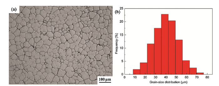
Fig. 1(a) shows the optical micrograph of the as-cast Mg-2Zn-0.2Y-0.5Nd-0.4 Zr alloy. It can be seen that the alloy consists of almost equiaxed grains and a small amount of second phases distributed discontinuously at the grain boundaries. As shown in Fig. 1(b), the grain size is estimated to range from 8.2 to 76.5 μm. The average value is about 39.9 μm, which is smaller compared with that reported for the as-cast Mg-1.5Zn-0.6 Zr (wt%) [30], Mg-1.5Zn-0.6 Zr-2Er (wt%) [30], and Mg-2Zn-0.46Y-0.5Nd (wt%) [21]. The second phases distributed inside the grains are also observed. However, the volume fraction of the second phases is too small to be detected by XRD. From DSC curve of the as-cast alloy, as shown in Fig. 2, only one endothermic peak appears at temperature in the range of 497-510 °C upon heating, which indicates that this alloy contains only one kind of the second phase. The composition and structure of the second phase are further investigated by TEM analysis. Fig. 3(a) shows the TEM bright field image of a branch of the second phase near the trigeminal grain boundary. The location of energy dispersive spectrometer (EDS) is marked as A in Fig. 3(a). EDS result (Fig. 3(b)) shows that the second phase mainly contain four elements of Mg, Zn, Nd and Y, in which the content of Y is much less than that of other three elements. Fig. 3(c-e) shows the SAED patterns recorded from different zone axes for the second phase shown in Fig. 3(a). Through analyzing SAED patterns, the second phase can be indicated as the pseudo-ternary T phase. The structure of T phase with a = 0.96 nm, b = 1.12 nm, and c = 0.94 nm, which was first identified in Mg-8Zn-1.5 MM (wt%) alloy [31,32]. As reported by Wei et al. [31], T phase has a wide range of compositions in Mg-Zn-MM alloy systems. The lattice parameters for T phase also vary slightly with alloy composition. Obviously, the lattice parameters (a = 0.99 nm, b = 1.20 nm, and c = 0.96 nm) of the T phase in Mg-Zn-Y-Nd-Zr alloy calculated from the SAED patterns is a little larger than that reported in Mg-8Zn-1.5 MM (wt%). The reason for this may be that the T phase contains rare earth element Nd with larger atomic size, which results in an increase in lattice parameters.
Fig. 1. (a) Optical micrograph of the as-cast Mg-2Zn-0.2Y-0.5Nd-0.4 Zr alloy and (b) corresponding grains size distribution histogram.
Fig. 2. DSC curve of the as-cast Mg-2Zn-0.2Y-0.5Nd-0.4 Zr alloy.
Fig. 3. (a) TEM bright field image of the second phase at grain boundary for the as-cast Mg-2Zn-0.2Y-0.5Nd-0.4 Zr alloy; (b) EDS result of region A in (a); (c), (d), and (e) SAED patterns of regions B, C, and D in (a), taken from the [
According to DSC analysis (Fig. 2), the second phase, which is identified as T phase in the as-cast Mg-2Zn-0.2Y-0.5Nd-0.4 Zr alloy has higher melting temperature and stability than Mg-Zn binary phases observed in the as-cast Mg-5Zn-0.6 Zr (wt%) [32], Mg-6Zn-0.5 Zr (wt%) [33], and Mg―2Zn―0.46Y―0.5Nd (wt%) [21]. As suggested by Hänzi et al. [4,18], the growth-inhibiting potential of the stable second phases in Mg-Zn-Y alloys (i.e., Mg3YZn6 in ZW21 and Mg12YZn in WZ21) can be deployed at elevated temperatures, which allows the application of forming procedures and heat treatments. Similarly, the stable second phase (T phase) precipitated in the present alloy is also expected to restrict the grain size in subsequent micro-tubes processing, in which Mg alloy materials are subjected to thermo-mechanical processing steps, i.e., hot extrusion, multi-pass cold drawing and recrystallization annealing [34,35].
Fig. 4shows the tensile engineering stress‒strain curves of as-cast alloy specimens at room temperature. The mechanical properties including yield strength (YS), ultimate tensile strength (UTS), and fracture strength, are listed in Table 1. For comparison, the data reported for several typical Mg-Zn base alloys are also summarized in Table 1. It is seen that YS, UTS and fracture elongation of Mg-2Zn-0.2Y-0.5Nd-0.4 Zr alloy are about 89 ± 7 MPa, 203 ± 5 MPa and 35% ± 3%, respectively. The tensile strength of the present alloy is higher than that of as-cast Mg-Zn binary alloys [36], and reported RE-bearing Mg-Zn base alloys [23,[37], [38], [39], [40]]. In particular, the fracture elongation value is much larger than that of other as-cast Mg base alloys [14,[37], [38], [39], [40], [41], [42], [43], [44]]. As observed in Fig. 1, the less continuity of intergranular phase contributes to the good ductility, because it can release stress concentration at grain boundaries caused by the difference of deformation magnitude between matrix and second phase and prevent the formation of micro-cracks along grain boundaries. As a result, the fracture mode of this alloy is mainly transgranular ductile fracture, and lots of dimples as well as tear ridges are observed on the fracture surface, as shown in inset of Fig. 4. On the other hand, the relative small grain sizes which yield more grain boundaries can reduce the overall stress concentration and accommodate anisotropic plastic strain, thus bring out the ductility improvement at room temperature [45,46].
Fig. 4. Tensile engineering stress‒strain curves of three specimens for the as-cast Mg-2Zn-0.2Y-0.5Nd-0.4 Zr alloy, the inset is SEM fractograph after tensile test.
Table 1 Mechanical properties of the as-cast Mg-2Zn-0.2Y-0.5Nd-0.4 Zr alloy and several typical as-cast Mg alloys reported previously. YS and UTS are yield strength and ultimate tensile strength, respectively.
| Alloys | YS (MPa) | UTS (MPa) | Fracture elongation (%) | Ref. |
|---|---|---|---|---|
| Mg-2Zn-0.2Y-0.5Nd-0.4 Zr | 89 ± 6 | 203 ± 5 | 35 ± 3 | This work |
| Mg-2.0Zn | 27 ± 2 | 145.9 ± 3 | 12.23 ± 1.5 | [36] |
| Mg-4.0Zn | 58 ± 1.5 | 216.8 ± 10 | 15.8 ± 5.5 | [36] |
| Mg-4.0Zn-0.2Ca | 58.1 ± 1 | 225 ± 5 | 17.5 ± 1 | [36] |
| Mg-4.0Zn-2Ca | 90 ± 4 | 143 ± 5 | 2.1 ± 0.2 | [36] |
| Mg-1.0Zn-1Mn | 44 | 174 | ˜$\widetilde{1}$2 | [37] |
| Mg-2.0Zn-1Mn | ˜$\widetilde{6}$0 | ˜$\widetilde{1}$80 | $\widetilde{1}$1 | [37] |
| Mg-2Zn-0.46Y-0.5Nd | 105 | 209 | 10.6 | [23] |
| Mg-2.5Zn-0.3Ca-0.4La | 77 | 164 | 7 | [38] |
| Mg-4.5Zn-1Y-3Nd-0.5 Zr | - | 219.2 | 11 | [39] |
| Mg-3Zn-0.9Y-0.6Nd-0.6 Zr | 119 | 180 | 12.3 | [40] |
| Mg-6.0Gd-1Zn | 144 ± 1.4 | 144 ± 1.4 | 8 ± 1.2 | [41,42] |
| Mg-6.0Al-1Zn (AZ61) | 121 ± 2.4 | 218 ± 8.1 | 10 ± 1.2 | [42] |
| Mg-3.0Gd-3.0Al-1Zn | 121 ± 2.4 | 218 ± 8.1 | 10 ± 1.2 | [42] |
| Mg-5.0Zn-0.6 Zr | 88 | 236 | 18 | [32] |
| Mg-5.0Zn-2Nd-0.6 Zr | 102 | 134 | 3 | [32] |
| Mg-5.0Zn-2Nd-1Y-0.6 Zr | - | 220 | 12 | [32] |
| Mg-3Nd-0.2Zn-0.5 Zr | 92 | ˜$\widetilde{2}$25 | 9.5 | [43] |
As well known, the basal <a> slip in Mg and Mg alloys occurs with substantial ease in comparison with other slip systems due to its lower critical resolved shear stress (CRSS). However, the basal <a> slip only provides two independent slip systems, which is far fewer than the necessary five independent systems for homogenous deformation in a polycrystalline material [47]. Therefore, such a large fracture elongation of Mg-Zn-Y-Nd-Zr alloy cannot be expected if the basal slip system is the sole mechanism of plastic deformation. From Fig. 4, it is noted that there exists two stages with different characteristics during plastic deformation. At the initial stage, flow stress increases rapidly with the increase in plastic strain. Namely, the alloy shows a well-balanced work hardening. At the later stage, the stress remains almost a constant with the increase in plastic strain. In order to further reveal the underlying cause of high plasticity, the microstructure and deformation mechanisms at two different stages have been investigated. The specimens after a plastic strain of 5% and 35% corresponding to two stages are selected to be analyzed, respectively.
For the tensile specimen subjected to a strain of 5%, a set of parallel slip lines of dislocations is observed in Fig. 5(a). These dislocation lines are considered to lie on the basal plane because of its lower critical resolved shear stress (CRSS) than other slip systems. Similar parallel slip lines of basal dislocation have also been observed by Koike [46]. Another important feature of microstructure observed is deformation twinning. Fig. 5(b) presents typical TEM bright field image revealing that the parallel twin platelets are formed. Their orientations inferred from the corresponding dark field image are different from the matrix, as shown in Fig. 5(c). Since the boundary between a twin and its parent orientation has a distinct axis and angle of misorientation, the type of twinning can be determined by the EBSD analysis. Fig. 6(a) shows the EBSD Euler map for the tensile specimen subjected to a strain of 5%. Compared to microstructure of the as-cast specimen shown in Fig. 1, there exists no significant change of grain shape and size. Fig. 6(b) displays the distribution of boundary misorientation without considering the boundaries angles below 5°. It is seen that almost all the grain boundaries are high angle grain boundaries (HAGBs) with misorientation angles higher than 20°. Only one peak appeared at about 86°, suggesting that the twins are {10 - 12} (86.3°) extension twins.
Fig. 5. TEM bright field images of the as-cast Mg-2Zn-0.2Y-0.5Nd-0.4 Zr alloy after a plastic strain of 5% showing (a) dislocations and (b) twins; (c) TEM dark field image of the squared region in (b).
Fig. 6. (a) EBSD Euler map and (b) misorientation distribution of the as-cast Mg-2Zn-0.2Y-0.5Nd-0.4 Zr alloy after a plastic strain of 5%.
Twinning has been known to be an important coordination deformation mechanism in Mg alloys. If only the basal slip occurs in Mg alloys, the plastic heterogeneity is very strong, which may give rise to a large plastic compatibility stress. The local stress results in the activation of twinning. In general, {10 - 12} extension and {10 - 11} contraction twins are the two typical deformation twinning systems, although other twinning systems have been experimentally observed in Mg alloys. As reported by Koike [46] and Chino et al. [48], {10 - 12} twinning easily occurs at the initial stage of plastic deformation in a relatively large-grained sample (tens of microns) in order to accommodate concentrated stresses due to basal dislocation slip. Similarly, for the present deformed Mg alloy, only the {10 - 12} twins are observed while {10 - 11} twins have never been found [46,48]. The cause for the formation of {10 - 12} extension twinning can be attributed to their small CRSS. Previous researches [49,50] have discussed that the CRSS for the activity of {10 - 12} twining is only about 2 MPa, which is far less than 114 MPa required for {10 - 11} twinning. This extension twinning can improve the ability of coordination deformation. On the other hand, the onset stress for twinning is larger compared to stress necessary for dislocation glide. When twins are formed, twinning boundaries would act as barriers for dislocation slip, and thus become a source of work hardening. Yoo [47] reported that twinning inferfaces, the {10 - 12} and {11 - 21} in particular, are repulsive to basal dislocation slip, which results in an increase in flow stress. Therefore, the activity of {10 - 12} extension twinning is also responsible for the obvious work hardening behavior observed at the initial stage of plastic deformation.
For the specimen subjected to 35% plastic deformation, plentiful dislocation lines are disorderly distributed in the crystal which forms the complex network, as can be seen in Fig. 7(a). Fig. 7(b) is the corresponding dark field image. It is clear that the subgrain with different orientation is formed in matrix and the subgrain boundary is made up of dislocation tangle. Fig. 8(a) shows the EBSD Euler map suggesting that substructures with different orientations divide the coarse grains into numerous subsections. Fig. 8(b) displays the distribution of boundary misorientation. Obviously, the frequency of low angle grain boundaries (LAGBs) with misorientation angles below 10° abundantly increases to 34.8%. The proliferation of LAGBs also means the emergence of substructure, which is in good agreement with the TEM result.
Fig. 7. (a) TEM bright field image and (b) corresponding dark field image of the as-cast Mg-2Zn-0.2Y-0.5Nd-0.4 Zr alloy after a plastic strain of 35%.
Fig. 8. (a) EBSD Euler map and (b) misorientation distribution of the as-cast Mg-2Zn-0.2Y-0.5Nd-0.4 Zr alloy after a plastic strain of 35%.
As shown in Fig. 7(a), plentiful dislocations existing in the substructure indicate that the non-basal slip systems are activated besides basal slip system. Here, the non-basal slip systems are investigated by high resolution TEM (HRTEM) with the inverse fast Fourier transform (IFFT). Fig. 9(a) presents the HRTEM image of a representative dislocation region viewed along the [1 - 21 - 3]Mg zone axis. Fig. 9(b) shows the corresponding fast Fourier transform (FFT) diagram. By using IFFT, the lattice images of the reflection of (0 - 1 11) and (1 - 1 01) crystal faces are obtained as shown in Fig. 9(c) and 9(d), respectively. A certain number of additional half-plane of atoms, observed in (0 - 1 11) and (1 - 1 01) planes, indicates that the pyramidal {1 - 1 01} slip systems apart from basal {0001} slip systems can also slip along the close-packed direction of <11 - 20 > . It is thus suggested that the activation of the {1 - 1 01} slip system are feasible during the plastic deformation. The reason for activation of the non-basal pyramidal slip systems can be understood from two aspects. First, the generalized stacking fault energy (SFE) determines the nucleation of the non-basal dislocations. Sandlöbes et al. [51,52] reported that the reduced intrinsic SFE by the addition of Y causes the formation of intrinsic stacking fault which acts as heterogeneous nucleation source for pyramidal dislocations. Zhang et al. [53] calculated the {11 - 22} <11 - 23> generalized SFE of a wide range of Mg-based binary alloy systems and found that the alloying elements, i.e. Zn, Nd, Er, etc., are effective in decreasing the unstable SFE of pure Mg. In the case of Mg-Zn-Y-Nd-Zr alloy, the mixed addition of Zn, Y, and Nd is in favor of the lowering of SFE and thus promotes the nucleation of non-basal dislocations and activation of non-basal slip systems. Second, the non-basal slip can also be ascribed to the plastic compatibility stress associated with grain boundaries. Activation of the non-basal slip systems by plastic compatibility stress has been well-established by Koike et al. [46,54]. They suggested that basal slip and non-basal slip were shown to occur nearly at the same ease when the basal planes were tilted in such way that the Schmid-factor ratio (equivalent to the critical resolved shear ratio) of non-basal slip system to basal slip system was large enough. For example, non-basal dislocations generated at grain boundaries under compatibility stress were observed in AZ31 alloy with an average grain size of 50 μm during tensile deformation by Kobayashi et al. [55]
Fig. 9. (a) HRTEM image of the as-cast Mg-2Zn-0.2Y-0.5Nd-0.4 Zr alloy after a plastic strain of 35% viewed along the [
The microstructure, mechanical properties and deformation mechanisms of as-cast Mg-2Zn-0.2Y-0.5Nd-0.4 Zr (wt%) alloy for stent applications have been investigated. The as-cast microstructure comprises almost equiaxed and refined grains with average size of about 40 μm and a small amount of second phase (T phase) distributed discontinuously either at the grain boundaries or inside the grains. The ultimate tensile strength and fracture elongation are up to 203 MPa and 35%, respectively. Such a high tensile plasticity is rarely observed in as-cast Mg alloys. During tensile deformation, there exist two different deformation stages. At the initial stage, the plastic anisotropy caused by basal slip produces compatibility effects, which prompts the activity of {10 - 12} (86.3°) twins. This twinning can improve the ability of coordination deformation. At the later stage, non-basal pyramidal slip systems are formed which is considered to be ascribed to the reduced SFE as well as the plastic compatibility stress associated with grain boundaries. Activity of pyramidal slip provides more independent slip systems, which can accommodate strain along <0001> direction. In addition, it is expected that the stable second phase (T phase) precipitated can restrict the grain size during forming process and heat treatment, and thus restore and even improve mechanical properties. As a result, sufficient ductility and stable second phase of the present Mg alloy, is of particular advantage for the subsequent processing of micro-tubes for biodegradable stents.
This work is supported by the National Key Research and Development Program of China (No. 2017YFB0702504), the National Natural Science Foundation of China (Nos. 51501166 and 51171174), and Outstanding Young Talent Research Fund of Zhengzhou University (No. 1421320046).
The authors have declared that no competing interests exist.

 WeChat
/
| 〈 |
|
〉 |


