Search for articles:
Xiaochen Zhou , Zhili Sun
Corresponding authors:
Received: 2018-12-29
Revised: 2019-04-28
Accepted: 2019-05-26
Online: 2019-11-05
Copyright: 2019 Editorial board of Journal of Materials Science & Technology Copyright reserved, Editorial board of Journal of Materials Science & Technology
More
Abstract
Endovascular repair of the thoracic aorta with self-expanding stent-grafts has been emerging as a less invasive alternative treatment compared with conventional open surgeries. Despite the promising efficacy and safety of endovascular stent grafting, the stent-graft failure remains a major concern in terms of stent migration, device fatigue, and the risk of endoleaks. Challenges associated with the stent-grafts involve optimized geometrical structure, lifetime fatigue resistance, and adequate radial support. In this work, a novel endovascular stent-graft system is developed specially for the treatment of Stanford type B thoracic aortic dissections (TAD). Numerical study with finite element analysis (FEA) was utilized to evaluate the mechanical behaviors of the individual stent component. Results of the simulation were validated by experimental tests. Based on the systematic analysis of the parametric variations, a final stent-graft system was developed by the selection and arrangement of the individual stent components, targeting an optimal performance for treatment of TAD. The optimized solution of the stent-graft system was tested in clinical trials, showing advantageous therapeutic efficacy.
Keywords:
Thoracic aortic dissection (TAD) is one of the most common and catastrophic manifestations of the acute aortic syndrome. TAD occurs when a tear of the intima (the inner layer) allows blood to channel into the aortic wall, separating the layers of tissues and creating two passages for blood: a true lumen and a false lumen [1]. According to the commonly used Stanford classification, the TAD can be divided into two groups, type A and type B. Type A dissection denotes any involvement of the ascending aorta, while type B indicates a dissection limited to the descending aorta [2]. While open surgeries are still reserved for treating type A TAD due to the complexity of the anatomy in the ascending aorta, thoracic endovascular aneurysm repair (TEVAR) has been widely used in the treatment of various aortic pathologies, including type B dissections [[3], [4], [5], [6], [7]]. In TEVAR intervention, a stent-graft (SG) system is crimped into a sheath and then guided from the femoral artery to the diseased artery segment. Upon releasing, the stent-graft will expand to seal off the affected aorta from the blood pressure, which eliminates the blood circulation through the false lumen. Compared to open surgical approach, TEVAR is minimally invasive and has demonstrated a clear benefit of lower perioperative mortality and morbidity in randomized controlled trials [8].
Worldwide, approximately 70% of the aortic aneurysms or aortic dissections are abdominal aortic aneurysm (AAA) while 20% are thoracic aortic aneurysm (TAA) and 10% are TAD. Therefore, most of the current stent-graft systems are primarily tested and designed to treat aortic aneurysms (AAA or TAA), which are essentially different from TAD. Only a few stent-graft systems are specially designed for the treatment of TAD. One example is the Medtronic Valiant® thoracic stent graft, a product designed mainly for TAA treatment, although in certain cases it can also be used to treat TAD. However, the situation in China is opposite: TAD accounts for 70% of the aortic aneurysms or dissections. As a result, a TAD-specific stent-graft system is more urgently needed in China.
Most of the stents used in TEVAR are made of nitinol alloys due to their superior biocompatibility [[9], [10], [11]], good resistance to corrosion and fatigue [12], and excellent mechanical properties [13]. There have been extensive investigations on the nitinol stents based on experimental tests [[14], [15], [16], [17]]. In the past, numerical simulation with finite element analysis (FEA) was proven to be a promising strategy in the evaluation, design and optimization of nitinol stents [[18], [19], [20], [21], [22], [23], [24], [25], [26], [27], [28], [29], [30]]. Rebelo et al. showed that FEA was able to capture the nonlinear mechanical response of nitinol using user defined materials property in Abaqus [24]. Scherer et al. introduced the input and output parameters for FEA models for proper quantifying the stent-graft system [29]. Nematzadeh et al. studied the effect of materials variations on the stent’s both mechanical and clinical performance based on FEA [21]. Bending behaviors of aortic stent-grafts were simulated and compared between spiral nitinol stents and traditional Z-stents to address the risks associated with the flexibility [19,27]. Eight marketed aortic stent-grafts were simulated under the framework of FEA by Demanget et al., which implies how the stent design could affect the mechanical performances [23]. Since the stent-grafts are subject to very high cycles of loading from systolic-diastolic pulsations, the lifetime fatigue performance is of vital importance. Auricchio et al. reported the approach using FEA and fatigue analysis to access the lifetime of ballon-expandable stents [18]. Clearly, one of the advantages of FEA is the cost and time efficiency, especially in the parametric or optimization analysis. Puertolas et al. employed the FEA approach to develop a methodology of designing a customized colonic stents, where they could vary the radial stiffness along the longitudinal axial as desired [26].
The primary function of the stent-graft system is to exclude the affected artery segment completely from the impact of the pulsatile blood flow. In order to achieve this function, a positive sealing of the stent-graft in the aortic wall is imperative, especially in the proximal end due to the fact that the tear almost always happens there [1]. In the current available stent-graft systems like Medtronic Valiant®, a minimum of 15 mm seal zone in the proximal neck is required prior to implantation [31]. A seal zone less than 15 mm could increase the short- or long-term risk of endoleaks of migration of the stent-graft. Seal zone extension using other methods should be performed prior to the TEVAR treatment for those with seal zone less than 15 mm [32].
The above-mentioned shortcomings and limitations of the current endovascular stent-graft systems promoted the initiation of this work: to develop a novel stent-graft system targeting specifically the treatment of TAD and aiming to shorten the minimal length of the seal zone. Numerical study with finite element analysis was performed systematically to each of the stent components. The purpose of the simulation is to gain insight into the effect of the parametric variations on the final performance of the stent, mainly on the fatigue safety under pulsatile loading and the radial force exerting on the aorta. Experimental tests to measure the fatigue and radial forces were carried out to validate the numerical results. Based on the numerical studies, a novel stent-graft system was created by the careful selection and arrangement of the stent components. Finally, the optimal solution was tested in animal tests and clinical trials to verify the design.
The self-expanding stent-graft system presented in this work is specially designed for TAD. This SG system managed to reduce the length of seal zone to only 7.5 mm, which ensures it being used to treat more patients without extending the seal zone. The present stent-graft system consists of Dacron graft material and Nitinol stent components. The stent components are formed by winding a straight nitinol wire over a series of fixed pins on a cylindrical surface, followed by a heat treatment, to generate the basic structural shape. The open ends of each component are connected using a small nitinol tube to make a closed loop. These stent components are then stitched on a smaller cylindrical graft material, as shown in Fig. 1(a).
Fig. 1. Stent-graft and its components: (a) full stent graft; (b) V-type stent; (c) W-type stent.
Two patterns of the stent strut are designed to be used at different locations of the stent-graft system: V-type and W-type. V-type stents are made of one single V-strut as Fig. 1(b) shows. W-type stents are made of two kinds of V-struts with the height of 7.5 mm and 5.0 mm alternately, which is shown in Fig. 1(c). Seven series of stent components are designed, among which five are V-type stents while the rest two are W-type stents. The nomenclature of the designed stent components is explained here: the name X-Y-Z: X represents the nominal diameter of the component (the diameter of the cylindrical surface of graft material), Y represents the height of the V- or W-strut, and Z represents the diameter of the nitinol wire. For example, X-50-0.33 refers to a V-type stent with 50 mm strut height and 0.33 mm wire diameter.
In TEVAR, the oversize is defined as [33]:
Oversize=$\frac{Nominal diameter of the SG-Inner diameter of Aaorta}{Inner diameter of Aorta}$ (1)
For a stent-graft oversize less than 10%, an increasing risk of endoleak type 1 is reported by Mohan et al [34]. For a stent-graft oversize greater than 30%, the potential migration of the stent will increase according to the clinical study by Sternbergh et al [35]. Senf et al. demonstrated that oversize has a great impact on the radial forces of the stent with a finite element sensitivity study [20]. Taking all these work into consideration, each experimental nitinol stent component was designed with a stent-graft oversize between 10% and 30% as shown in Table 1. As the nominal diameter (X) increases, the peak number has to increase accordingly to maintain the consistent radial force. Table 2 lists the peak numbers of all the stents.
Table 1 The correspondence among stent, sheath and aorta.
| Nominal diameter (mm) | Inner diameter of sheath (mm) | Inner diameter of aorta (mm) | Stent graft oversize |
|---|---|---|---|
| 20 | 4.8 | 16 | 25% |
| 22 | 4.8 | 18 | 22% |
| 24 | 5.4 | 20 | 20% |
| 26 | 5.4 | 22 | 18% |
| 28 | 5.4 | 24 | 17% |
| 30 | 6.1 | 26 | 15% |
| 32 | 6.1 | 28 | 14% |
| 34 | 6.1 | 30 | 13% |
| 36 | 6.1 | 32 | 13% |
| 38 | 6.7 | 34 | 12% |
| 40 | 6.7 | 36 | 11% |
| 42 | 7.4 | 38 | 11% |
| 44 | 7.4 | 40 | 10% |
| 46 | 7.4 | 42 | 10% |
Table 2 Peak numbers of all the stents.
| Sample | Nominal diameter (mm) | |||||
|---|---|---|---|---|---|---|
| 20, 22 | 24 | 26, 28 | 30, 32, 34, 36 | 38, 40 | 42, 44, 46 | |
| X-50-0.33 | 10 | 10 | 10 | 12 | 12 | 16 |
| X-75-0.33 | 10 | 10 | 10 | 12 | 12 | 16 |
| X-75-0.38 | 10 | 10 | 10 | 12 | 12 | 16 |
| X-150-0.33 | 5 | 5 | 5 | 6 | 6 | 8 |
| X-150-0.43 | 5 | 5 | 5 | 6 | 6 | 8 |
| X-7550-0.33 | 8 | 10 | 10 | 12 | - | - |
| X-7550-0.38 | 10 | 10 | 10 | 12 | 12 | 16 |
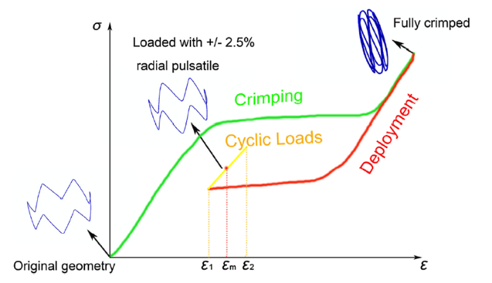
A finite element model was set up to simulate the deformation of the stent components described in the above section. As mentioned, during the TEVAR intervention, the stent-graft system is first crimped into the delivery catheter and then deployed at the diseased location to allow the stent-graft to expand to the inner diameter of the aorta. Once deployed, the stent-graft is subject to the cyclical loading due to the blood pressure. For this study, a ±2.5% radial pulsatile under 100 mmHg blood pressure difference was applied to the stent to simulate the worst-case scenario [12]. Fig. 2 shows the loading path of the simulation for each stent component.
Fig. 2. Loading path for the area around the peaks of the FEA simulation.
The geometry models of the nitinol stents were created in a commercial CAD software, SolidWorks 2012 and then imported to commercial finite element code Abaqus 6.13-1. The symmetry along the circumference allows to simulate only a repetitive section of the stent in order to reduce the model size. A static analysis was performed with nonlinear geometry option to account for the large deformation seen in the crimping and self-expanding processes. All the contact frictions were ignored in the analysis for simplicity. As the graft material is believed to have negligible effects on the overall mechanical response of the stent-graft systems [36], the graft was not included in the model.
In some FEA studies of the stents, the aorta and even the aneurysm are modeled together with the stent to simulate the actual scenario [37]. The introduction of an aorta model will significantly increase the computation time, making it less favorable for a systematic parametric study considering the number of stents being simulated. A simplified approach was employed in this simulation, which uses a virtual rigid cylinder surface (crimper) to decrease the stent diameter. An aorta model was simulated in the first two studies with the representative stent components to compare the difference between using a crimper and using a virtual aorta model.
Nitinol has a unique superelastic property [38]. A user material subroutine (UMAT) of Abaqus was used to simulate the superelasticity of the stent’s nitinol material. All the material parameters of the nitinol wire were based on their actual tests. The aorta that was used only in the comparison with the rigid crimper was modelled as a linear elastic material with Poisson’s ratio of 0.5 [36] and wall thickness of 2.0 mm. The modulus of elasticity was carefully adjusted with several iterations to achieve a 5% compliance between systolic pressure and diastolic pressure [12].
Fig. 3 shows the boundary conditions of the FEA model. In these simulations, cylindrical coordinates were used. A cylindrical rigid surface was modelled as the crimper. The crimper was used to compress the stent, control the self-expanding, and apply the pulsatile loading by altering its diameters accordingly. Circumferential degree of freedom was fixed at the open ends of the repetitive section of the stent component. Axial direction was fixed to prevent the rigid body translation. For the crimper, both circumferential and axial degrees of freedom are fixed. Self-contact may occur during the crimping process for some stent components, hence two additional rigid surfaces were added to make sure the repetitive section of the stent component deforms within its original central angle. For aorta models, the length of an aorta is three times of the height of a stent component in order to eliminate the boundary effect.
Fig. 3. Boundary conditions.
For the stent, the element type is C3D8R (8-node linear brick, reduced integration). There are 30 nodes along the circumference of the section (Fig. 4) and 1000 nodes along the axis of the repetitive section of the stent component. For the crimper and the two additional rigid surfaces, there are 100 × 100 SFM3D4R (4-node quadrilateral surface element, reduced integration) elements.
Fig. 4. Mesh across the section.
After the simulations, the Bose ElectroForce® 9150-6 dynamic fatigue testing machine was used to measure the radial forces. A 400 million-cycle (10 years in vivo) accelerated fatigue test (by improving the frequency to 33 Hz) was designed for all the stent components, which took almost 3 months. The experimental fatigue test was carried out by controlling the pressure to achieve a ±2.5% radial pulsatile. The environment temperature was set as 37 ± 2 °C and the fatigue tests were run at the frequency of 33 Hz. X-150 series stent components were chosen to measure their radial forces because they were most stable of all during the crimping procedure.
The same sizes of stents for human clinical trials were implanted into 12 sheep with the help of Beijing Anzhen Hospital according to ISO25539. All the procedures were completed successfully. 6 sheep were dissected after 28 days and the other 6 sheep were dissected after 180 days.
72 TAD patients have received surgical treatments using present TAD stent-graft systems in ten hospitals. All the surgeries were approved by the Ethics Committees of Chinese PLA General Hospital (2013-0306), Zhongshan Hospital (2014-16), the Second Xiangya Hospital of Central South University (2014-09), the First Affiliated Hospital of Zhejiang University (2014-30), the 2nd Affiliated Hospital of Harbin Medical University (2013-029), Shandong Provincial Hospital (2014-01), the First Affiliated Hospital of Sun Yat-sen University (2013-027-06), the First Affiliated Hospital of Fujian Medical University (2014-001-02), General Hospital of Ningxia Medical University (2014-8) and Xijing Hospital (QX20150108-1). All patients were observed for 1 year after operation. CT results were carried out by Toshiba CT Aquilion One. The slice increment was 1 mm.
To validate the numerical model, experiments were conducted to measure the radial force of the stent components during crimping and deployment to compare with the numerical results. The loading and unloading rate were both set as 0.4 mm/s and the temperature of the holder was set as 37 °C. Components with the nominal diameter of 22, 28, 36, and 40 mm of the 150-0.43 series were chosen for experimental tests.
Fig. 5 shows the comparison between the FEA simulations (black) and test results (red). Discrepancies are observed on the loading path when the stent is crimped. Many factors can cause the discrepancies such as the neglect of the friction between the stent and the crimper, the difference between the idealized crimper and the machine, the asymmetry during the actual loading and unloading procedures and the testing machine’s own error. On the unloading path, FEA predictions show a much better agreement with the experiment results. The unloading paths are of greater interest in stent applications because the fatigue process takes place there. The deformation from the tests was not uniform because the initial ratio of the stent diameter and height was large, which made the process not quite stable. This explains why the curves were much less smooth for the smaller diameter stent. Another reason for the rough curves is that nitinol is a thermo-mechanical coupled material. In these tests the stents were heated by the holders which were maintained at 37 °C, but this was not enough considering the stents also had direct contact with the atmosphere. The rapid fallings at the beginning of the unloading procedure shown in Fig. 5 are caused by the frictional effect in the equipment (plate on plate). Negative radial forces were removed and only positive numbers were kept. This led to the deviation between the initial and final stent diameter after deployment. The deviation of radial forces between the loading and unloading path is caused by the system error of the testing equipment. In this case the system error is about 1 N. The system error is mostly introduced by the friction between the parts of the fixture. The experiment results were acceptable in general.
Fig. 5. FEA radial forces vs. experimental results: (a) 22-150-0.43; (b) 28-150-0.43; (c) 36-150-0.43; (d) 40-150-0.43.
During the crimping simulation, X-50 and X-75 series stents was found to have the most serious self-contacts because they have more peaks, which made them the quite unstable. As a result, when an X-50 or X-75 series stent were used, the crimping and self-deployment processes must be operated very cautiously.
For V-type stents, despite the differences in the strut dimensions, the highest tensile strain always occurs around the apices of the stents and the highest compressive strain occurs at the inner side of the apices (Fig. 6(a)), which is expected as these areas have the most severe curvatures. As a comparison, for W-type stents, the highest tensile strain occurs around the apices of the lower peaks (Fig. 6(b)). Since fatigue fractures are mostly caused by tensile strains rather than compressive strains [39], all the calculations in this work are based on tensile strain. The maximum strain of all stents simulated (Table 2) after crimping to the sheath was 9.94% for stent 46-7550-0.38.
Fig. 6. Maximum strain contour plot: (a) V-type stent; (b) W-type stent.
After implantation, the fatigue failure under pulsatile loading is key to the overall performance of the stent-graft system. It was reported that the oscillating strain magnitude contributes more to the stent’s fatigue behavior [36,40]. Hence the results from numerical study were analyzed in terms of maximum principal strains in the stent [40]. The maximum principal strain at the systolic pressure was defined as ε1 and the one at the diastolic pressure was defined as ε2. We have:
εmean=(ε1+ε2)/2 (2)
εalt=|ε1-ε2|/2 (3)
where εmean and εalt are the mean strain and alternating strain, respectively.
Pelton et al. [41] provided a constant-life diagram from the diamond stent component fatigue tested up to 107 cycles. Then Pelton proposed the nitinol fatigue strain limit curve at 107 cycles based on his earlier experiments [41]. Early et al. [42] and Kleinstreuer et al. [36] provided separate curves also based on Pelton’s experiments. The fatigue criterion used in this work is shown in Fig. 7, which is similar to Kleinstreuer’s: for εmean less than 2%, the fatigue strain limit is 0.4%. As the εmean goes above 2%, the fatigue limit will increase by a slope of 0.1 because martensitic was found to have higher fatigue-crack thresholds and slower crack-growth rates compared to stable austenite and superelastic austenite [43,44].
Fig. 7. Fatigue limit of 107 cycles.
In this simulation, after the stent component is crimped and deployed to the inner diameter of the aorta, pulsatile loading is simulated by changing the stent diameter at systolic and diastolic pressures. Post-processing Python scripts were used to calculate the mean strain (εmean), the alternating strain (εalt), and the fatigue safety factor (FSF), which is defined as the ratio of fatigue strain limit and the alternating strain [40]:
FSF=$\frac{ε_{lim}}{ε_{alt}}$ (4)
3.3.1. Effect of stent structure on the fatigue safety factor
Fig. 8(a) and (b) is the contours of post-processing results for V-type and W-type stents. Results of the contours indicate that the areas of the lowest FSFs coincide with the areas of the highest strains. The contours of the reciprocal of FSFs were plotted for legibility.
Fig. 8. FSF contour plot: (a) V-type stent; (b) W-type stent.
One way to measure a stent’s fatigue safety is to plot the mean strain and alternating strain of all the FEA nodes on a constant life diagram [45]. However, considering the number of stents in this work, a more efficient method is used. To quantify the stents’ fatigue safety, fatigue safety factor (FSF), which is defined as the ratio of fatigue limit and alternating strain, is calculated [40]. The location on the stent with the lowest FSF represents the fatigue safety of the whole stent.
Fig. 9 shows the fatigue safety factor of all the stents simulated. As is seen, all the fatigue safety factors are above 1, indicating that all the stents stayed below the fatigue limit within 107 cycles theoretically.
Fig. 9. Fatigue safety factors of each series of stents.
For each series of stents, FSF decreases as the stent diameter increases, which means larger stents are more prone to fatigue. When the peak number increases (at nominal diameter 30 mm and 42 mm), the decreasing trend will slow down and even bounce for some series. It is obvious (Fig. 9) that stents made of smaller nitinol wires have higher FSF. For V-type stents, as the strut height increases, the FSF increases. Unlike other stents, X-75-0.33 series are designed for both thoracic and abdominal aortas. As a result, 20-075-0.33 with 6/8/10 peaks, 22-075-0.33 with 6/8/10 peaks and 24-075-0.33 with 6/10 peaks are designed.
3.3.2. Effect of taorta model on the fatigue safety factor
To testify the reliability of the fatigue models with a ±2.5% radial pulsatile loading, aorta models were introduced to the simulation of 36-050-0.33 to represent V-type stents and 36-7550-0.33 to represent W-type stents. The FSFs of 36-050-0.33 are 2.451 with aorta and 2.152 without aorta. The FSFs of 36-7550-0.33 are 2.998 with aorta and 2.762 without aorta. The introduction of aorta will increase the stiffness of the fatigue system so that the radial amplitude of the stent will be less than 5%. As a result, the FSF improves as expected. In other words, simulations without the actual aorta model accounts for a worst-case scenario in terms of the fatigue safety. Since all FSFs are above 1 without the introduction of aorta models, all the designed stents will be fatigue safe within 107 cycles.
In addition to fatigue performance, the radial force (RF) that the stent-graft system exerts on the aortic wall is another critical functional attribute to look at. The overall structural design of the device plays the largest role in the radial strength. The stent forces have been characterized in several different ways [46,47], including the COF (chronic outward force), RRF (radial resistive force), and RF (radial force). According to Maria S.C., et al, they are all somewhat related to the radial force [47].
The results of the calculated radial force of all the stent components are shown in Fig. 10. For all the series of stents, as the nominal diameter increases, the adjustment of peak numbers managed to keep the radial force at a constant level. Stents made of larger nitinol wires tend to provide larger radial forces due to the higher stiffness of the strut itself. Radial force decreases as the strut height increases due to the increased flexibility.
Fig. 10. Radial forces of each series of stents.
To this point, results of a systematic investigation have been presented, which shows that the structural design of the stents plays a critical role in the overall performance of the device, especially on the fatigue safety and radial force.
No significant migration was observed during the test. After 400 million cycles, the stents were removed from the simulated vessels and then observed under both a microscope of 10-20 times multiplication and an optical measuring instrument of 38 times multiplication, no fracture or collapse was found (Fig. 11). All the stents conserved their structural integrity.
Fig. 11. Surface topography of four sets of parallel samples under an optical measuring instrument of 38 times multiplication after 400 million cycles fatigue tests.
The results showed good endothelialization and no obvious vascular injury. Pathological sections (Fig. 12) showed no giant cells in the vessels and no obvious abnormalities in vascular smooth muscle and connective tissue. The results of animal trials proved the safety of the stent graft system.
Fig. 12. Pathological sections (a, b) after 28 days and (c, d) after 180 days.
None of the patients who were implanted with present TAD stent-graft systems suffered from endoleak at the proximal end (seal zone).
Here we took one patient with DeBakey I Standford A TAD for example: CTA vascular imaging was used to acquire pathological information including the length and diameter of the seal zone and the length of the pathological aorta. A 180 mm-long stent graft with the proximal nominal diameter of 36 mm and distal nominal diameter of 28 mm was chosen. Fig. 13 shows the CT (Computed Tomography) results of blood flow of a patient from Xijing hospital (Xian China). Before the surgery, the dissection started from the top of the descending aorta all the way to the abdominal aorta. After 30 days’ implantation, there was only a small part of blood near the distal end of the false lumen. The lower half of the true lumen without stent graft was still narrow. After 180 days, there was almost no sign of blood in the false lumen and the diameter of the true lumen was much wider. After 365 days, the blood flow was almost normal.
Fig. 13. Three-dimensional CT blood flow results of a patient’s thoracic aorta: (a) before surgery; (b) 30 days after; (c) 180 days after; (d) 365 days after.
The parametric variations of the individual stent components and their effect on the overall stent performance have been thoroughly analyzed in the last section. This knowledge is of vital significance in designing a TAD specific stent-graft system. In the following discussion, a stent-graft system (Fig. 14(b)) is created by a careful selection and arrangement of the individual stent components, with the TAD-specific considerations in mind.
Fig. 14. Stent graft for TAD: (a) Medtronic Valiant®; (b) present TAD stent-graft system; (c) Cuff for TAD.
(i) It was shown that the X-50 series stents have the largest radial forces and the lowest fatigue safety factors. The advantages of these stents are their lowest strut height, which means they can conform to a broad range of aortic anatomies. Younger patients tend to have steeper aortic arches; hence the conformability of the stent grafts must be good enough to fit these corners. Thus X-50 series are the best candidates for the treatment of the curving thoracic aorta.
(ii) The treatment of dissection requires weaker radial forces, compared with the treating of AAA and TAA, since the intima is too thin. Large radial forces at distal ends may lead to stent-graft induced new entry (SINE) [32]. As mentioned, the X-50 series’ radial forces are the largest among all the series, therefore the X-150-0.43 series are chosen to gentle the middle section of the stent. Additionally, it can also prevent the stent-graft system from embolism with the alternate arrangement of the X-50-0.33 series. The reason why X-150-0.43 was used instead of X-150-0.33 is that the radial force of latter is too small to support the true lumen.
(iii) In order to create a perfect seal in the aortic arch and shorten the previous 15 mm seal zone, both X-75-0.38 and X-7550-0.38 can be used as the first stent on the graft material. X-75-0.38 series have better fatigue resistance while X-7550-0.38 series can effectively reduce the seal zone to almost 5 mm as compared to the X-75-0.38 series. Clinicians can choose from these two designs based on their experience. The reduced seal zone feature empowers clinicians to offer TEVAR to more patients without the requirement of seal zone extension.
(iv) In contrast to aneurysms, the shape of true lumen of TAD is tapered due to the presence of false lumen. Correspondingly, the treatment for TAD requires tapered stent-grafts, different from the treatment for TAA. Tapered Dacron graft material was chosen and the diameters of stent components decreased gradually from the top to the bottom.
(v) The first bare stent at the proximal end is supposed to make the stent graft system easy to be delivered into the aorta and open the aorta long enough. By also taking the fatigue safety factors into account, an X-150-0.43 stent will be used.
(vi) For the last X-150 stent near the distal end, 0.33 mm was chosen to prevent SINE since smaller nitinol wires reduces the radial force of the stent. At the very distal end, an X-75-0.33 was used instead of X-75-0.38 for a proper radial force to prevent both backflow and SINE.
(vii) Fig. 14 shows the difference between Medtronic Valiant® (Fig. 14(a)) and present stent graft for TAD (Fig. 14(b)). Using X-50-0.33 and X-150-0.43 alternately will improve the conformability while maintaining an adequate radial force, which is especially important for thoracic aorta. The lower limit for proximal seal length has been shortened by 50%, from 15 mm to 7.5 mm.
(viii) Although all the stent grafts are carefully engineered, the possibility of endoleak type 1 at the proximal end still exists after TEVAR. In these scenarios, a cuff will be put inside the original stent graft as an extension to strengthen the sealing ability. The arch geometry for thoracic aorta requires larger radial forces to seal, therefore the stents with wire diameter of 0.38 mm are used (Fig. 14(c)).
The clinical trial has demonstrated very positive results of newly designed stent-graft system. The customizable feature of the system has greatly increased the flexibility and safety in treatment of TAD.
90 nitinol stent components were investigated with numerical simulations using finite element analysis. These stent components vary in terms of the strut type, strut height, peak number, wire diameter, and nominal diameter. The numerical model was validated through comparison with actual experimental tests. The results were systemically analyzed to show the effect of each parametric variations on the overall performance of the individual stent components, focusing on the critical attributes like fatigue resistance and radial strength. These findings were carried to the next phase to develop a TAD-specific stent-graft system by thoughtful selection and arrangement of the stent components. Featuring a customizable design, an increased conformability, a gentle radial support, and most importantly, a greatly reduced seal zone length, the experimental stent-graft system can empower the clinicians to offer TEVAR to a much broader range of aortic anatomies in treatment of TAD.
This work is jointly supported by the National Key R&D Program of China (No. 2018YFC1106600).

 WeChat
/
| 〈 |
|
〉 |


